Thursday, October 31, 2013

Land Rover valve train 2.5DT

Happy Halloween!

     Well to make a long story short, are you kidding me! It is and epic story! A true heroic tale!

    I went out this morning and brought the valve cover inside as it was 35F and then I cleaned it up and made a new cork gasket. After it warmed up to around 50F I went out and pulled the bolts from the valve train. Then I removed the rocker shaft assembly and refit the valve cover. It fit, so that meant the injectors were not blocking the cover from closing.
   Then the rocker assembly was refitted with the bolts a little over finger tight to keep it from moving. The cover was then refit. Lo and behold it would not seal???????? I discovered the other day that I have a spare diesel valve cover so I cleaned it up and then used it to check fit while the gasket sealant was drying on the original valve cover. Before I did this I verified that the shape and size and bolt holes were the same between the 2 covers. The only difference is where the breather hole is.
    Using this cover sped up the process as I needed not to worry about the gasket. So I set it in position on the head and using a deadblow hammer I tried to put it down in position(sealed). It would not go down something on the inside was not letting it. So taking the cover off I checked the inside for witness marks of the interferance. I saw 3 slight marks from the rocker arms of #3,7,and 8. Next I went in the house to check the part numbers online of the different 2.5 NA and DT rocker arms. I do have the correct parts.
   Then I took the old rocker arms out to compare with the new ones. That is when I discovered the difference.
   The new rocker arms are larger at the end where the adjusting screw goes in.

   You can see in the pictures that they are not even round. My parts came from Bearmach.

    The next step was to take the rocker shaft apart so the individual rocker arms were accessable.


    Once the arms were off I took them to my garage and using my flapwheel on the angle grinder I took off about 3/16" from each arm. Below are some before and after pics.


     The last pic even shows a witness mark from the inside of the rocker cover. On the outside of the nut end, the shiny bit by the oil hole.

    After putting the rocker shaft back together;


     It was time to refit to the head. Once again I used just slightly over finger tight and dropped the cover on. It went all the way down this time (I think!). Then I torqued it all down and re did the valve clearances to 010", installed the cover just over finger tight to set overnight.
     Tomorrow I hope to fill all the fluids and start it up. Then I can put the body work back on and maybe take it for a drive this weekend!
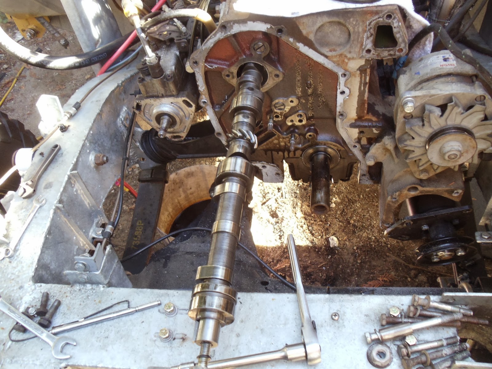
How I left it.

Wednesday, October 30, 2013

Land Rover valve train

   Well, I had wanted to let you know that the 109 was up and running but no,,,,,,,(*&$

    I was putting it back together and got as far as having all the hoses hooked up and decided to put oil in it. Standing on the drivers side and funneling oil thru the valve cover when I noticed a leak at the rear of the valve cover. So I tightend it down some more and put more oil in. There was none on the dipstick yet after pouring in almost a gallon.
   Going around to the right side I see that the entire side of the motor is covered in oil below the valve cover. So I dab around with a towel to clean it up and crank down on the valve cover again. Again oil starts pouring out the side. Ok I need a new gasket.
    So I made one from a sheet of cork. Then install it after much cleaning of oil. A quick dump of oil in the cover and it leaks out again. I stop and feel the edge of the gasket and there is about a 1/8" gap between the cork and the head. I tighten it down and can still feel the gap. I tighten all the way down, the gap won't change...WTF? I try a deadblow hammer, won't go down. I loosen all the injectors as they are really close. Won't go down. Hammer time again, won't go down. I check the inside of the valve cover and find witness marks from the head bolt on the #2 rocker block. Poking around I can feel a gap under the block itself and using a feeler guage find it is about .009". On the middle 3 blocks. The end blocks are flat.

     Then today I pulled the rocker shaft off and check the underside of the blocks, they middle 3 are all not flat. The 5 of them are all not the same thickness varing by .003". The bolt holes were clean so they didn't get hydraliced. The head bolts were all the same length.
     Then a friend came over who needed help and I didn't get back to it.


Monday, October 28, 2013

Land Rover 2.5DT coming together

     It was a bright day but the air was still chilly in the shade as I set about to get some few things done on the 109. There is a change in the air as Summer is finally leaving the Central California Coast.
    Today I wanted to button up as much of the motor as I could, fog was streching it's arms up the valley and rain was a threat for the next week. I put some clean engine oil in the tappets and slides, not wanting to use the engine assembly grease so as to not plug any oil passages.  I dragged out my head gasket and made sure I had the correct orientation, then the heavy head was moved from the garage to the car and I climbed into the engine bay and set it on the block. Next the pushrods were retrived from the wooden holder I had made to keep them in order, and slid into position. At this point head bolts were dropped into the holes to locate the head properly and a few turns of the  threads made by hand.
    The newly rebuilt rocker shaft was fitted. No, it wasn't perfectly set up. :^(  The # 6-7 rocker arms didn't line up on the valve stems, but neither did the holes for the  #4-5 blocks. So I just tapped the blocks over with a hammer and the rocker arms lined up! :^)
     Dropping the rest of the bolts inplace the torquing process was started. In the past I've just gone straight to 90ft-lbs and not had any issues. Lately I've been reading online of peoples torquing in sequence so I thought I would give that a go. The torque wrench set to 50ft-lb I went thru the entire 18 bolt sequence starting in the center and working outward as described in the manual. I reset the wrench to 35ft-lb and did the smaller bolts holding the rocker shaft blocks. Again the wrench was reset to 70# and the main bolts tightened, again reset to 90ft-lb and go thru the sequence a final time. Sure it took longer but in some way seemed easier than just going to 90#.
    Once the head was on the valves were set, again following the manual. Here is where I got concerned; in the manual the Defender 2.5DT is shown as having a .008" clearance, So I set mine up that way. Then while doing it I was thinking that I don't have that later valve train/ timing set up. So I checked the book and the earlier 2.5D has the same clearance as my 2.25D, .010". So I went thru it again setting the clearance to .010". Satisfied I put the valve cover on.
   
Next the waterpump was gooped up and installed, some of the easy electrical wires connected; water temp and fuel shutoff. The plug put back on the flywheel timing port, vent hose for crankcase.

     By then it was getting dark and cold so I quit for the night. The next day I had to attend a funeral so I would get nothing done. Julie, sorry to see you go! :-(

     Sunday came around and in the mid day I attended my grandsons season ending baseball game. After the game I dressed for the cool weather and went about installing the intake and exhaust system. Here the extra stud I had bought on Friday came in handy as I could replace the bolt used on the exhaust with the correct stud.
 
It took awhile to bolt on the intake then the exhaust with the turbo, I cleaned up the turbo hose inside and out . I reused the gasket from when I fixed the exhaust leak. The exhaust down pipe was also connected.

Then I moved over to doing the injectors, new domed washers were installed and all the soot removed from the injector nozzles. The injectors evenly torqued down to 14ft-lbs. The timing chest vent on the bottom of the chest was siliconed and installed. I even put on the heater hoses.


    There is still some tweaking to do with hose/wire placement, but as it was geting dark and the clouds moving in I stopped for the night. Most of the holes into the engine were now closed and rain not so much a concern. As I went into the house I felt the first drops falling.
    It did rain slightly last night, but we did have heavy winds, I'm glad to have gotten it all buttoned up so hopefully nothing got in the motor. More trace rain and wind expected for the next day or so. So I have updated the blog!

Thursday, October 24, 2013

Timing belt on Land Rover 2.5Dt

   I had to wait until the morning chill wore off today. It was in the mid 40's until around 1100. After a quick lunch I headed out and installed the camshaft oil seal. Since I didn't have the proper tool I used a machinist hammer and a depth guage to get the correct 1mm below the face depth. I checked it in about 8 places around the seal to make sure it was even.
    After that I put on the camshaft timing gear and then using the manual I went about setting the timing. Man, was it fussy! You have to have the timing pins out set the belt in place on the gears and set the tensioner, rotate the crankshaft 2 rotations and retighten the tensioner, reinstall the flywheel pin and see if it was still in time. The hardest part is when you put the belt on the crank and then the cam you can't get the slack out of it. By the time you get the belt around the pump gear the cam has moved the mark off by a half a tooth! Then once the tension is applied both the cam and pump are out 1 tooth or more. Frelling frustrating.
     I finally took the slack up by moving the cam and pump to the next tooth on the belt and when it was put on the pump and tensioned it lined up perfectly. Even after the 2 revolution and reset of the tensioner it was good. The pins all lined up and I went to torque the tensioner for the last time.
     That's went things went wrong. The nuts just kept on spinning and not tightening up I could feel that they were not "right". So I was thinking the stud had stripped in the aluminum and that would be a major setback. Luckily the stud came out with the nut and the nut had stripped threads on the stud.

     Of course I didn't have any M8x1.25 studs.....so I was off to my FLAPS. They had some but not the correct length. I bought 2 and would run a die down them and cut them to length. Or so I thought. Automotive studs are hardened. I couldn't hold them and re-thread them. Again disheartened at the "nothing is easy with this" attitude I changed out of my stinky oily work clothes into something clean and put on my motorcycle gear and rode to another auto parts place about 6 miles away.
     Ernie's Western Auto is a NAPA dealer and they had the correct studs for my repair. I was lucky as they had just came in the day before! So I bought 4, even though I needed 2.
    Going back home I changed back into the oily stinky clothes and went back at it. First putting in one of the studs and locking the tensioner in place. Then removing the other stud and replacing it. Next was 2 rotations of the crank and a check of all the timing pins. By George I'd done it!

     Putting the gasket on the timing cover with the Permatex anerobic goo and then the timing cover was preceded by setting the final torque on the camshaft gear, 30ft-lb IIRC.

Land Rover rocker shaft

     I am sure all my followers will remember that I only recieved a partial shipment of the rocker arms needed to repair the badly worn ones in my 2.5Dt. Well the rest of them came in a couple of days ago with the evening mail.
     So I set down a tarp on my living room floor, covered it with some paper towels and cautiously took it apart.


     I am begining to have a love-hate relationship with my workshop manual. I find it very poorly done, such as the jobs to do are not listed in an index but are grouped in a component. For instance if you want to find how to take the rockers off the shaft you have to wade thru the engine dissassembly chapter untill you get to that job. Something making it even more difficult for me is that I am finding  my engine seems to be a transition engine. It has design and components from the 2.5NAD and the 2.5Dt, making me flip back and forth in the manual. I finally realized this a couple of weeks ago when I was taking the motor apart. What I did to help was for the 2.5NAD section I highlited the edge of the pages in orange and the 2.5Dt were highlighted in pink. Now I can easily find the engine sections in the book as this is all that pertains to my 109.


     Back to the rocker rebuild! The mounting blocks were so tight I had to use a wedge to pry them apart so I could slide the blocks off. I set everything down in the order I took it off keeping the orientation of the ends. I did leave the end block on so I could have a reference point.
     Even though the rockers are labled inlet and exhaust there are 2 different styles of each and nothing to tell you where to put which one other than a drawing in the shop manual. It took me 2 tries to get it right, they look so similar. I had to use the wedge again to get the blocks back on. The other bit that slowed me down was the set bolt holding #2 block got cross threaded at some point(me?) and I had to run a tap and a die over all the affected bits(8mx1.25). I put engine assembly goop on all the bits as I was assembling them. I just hope after all that that they line up on the pushrods and valves when on the head.


Thursday, October 17, 2013

working on the Land Rover 109

     Well, I am still waiting on the camshaft oil seal and the last 4 rocker arms. They should have shipped from the UK yesterday/today. In the meantime I have been trying to do other things.
     I cleaned up the head by wire wheeling the soot off the valves and removing all the old gasket material. Good thing is no cracks, bad thing is one of the hot spots fell out. I found it in a box in the garage and pinned it back in.
    While doing the clean up I did see that #7 valve was really sooted up on the shaft. So using the valve spring compresser the valve was removed and cleaned up on the wire wheel and reinstalled. All the others look fine.
     I put the oil pan back on, using blue permatex. When I cleaned up the pan I coated the outside with spray on truck bed liner, hoping it holds up to the clanks and bangs of off road!


     I also removed the reciever style trailer hitch from my 88 and put it on the 109. This necessitated reaming out the top holes in the chassis to 7/16".


     I have to do the trailer wiring yet.
     The oil filter adapter was put on and a filter installed. I sure like the screw on kind! I hooked up the oil pressure guage and the warning lite wiring. Kinda funny--in the book when I looked up the oil filter number it just lists "screw on type".
    Earlier this week I purchased some RUD snow chains from Chain Stop www.chainstop.com . They were expensive including shipping around $250.00! for 2 sets. But if I need them I'll have em. I figured since I'll probably be going thru the Midwest this winter I'd better get some. I was disappointed to see they were mfg in China, I thought they were German. Probably just designed there.

Friday, October 11, 2013

Land Rover 19J motor going back together

All right already!!! I started to put the motor back together!!! First I had to set the camshaft endfloat. A rather laborous task putting on then taking off the camshaft timing gear. OK, so I put the camshaft in first, assembled with a light coating of assembly grease. Then with a dial indicator pulling the cam in and out to see how much it moved.
After doing that I could put on the timing chest. I used The Right Stuff to make my gasket. Fastening the bolts to the block and the DPS pump.Next up was to put in the new tappet guides and rollers and tappets. They started off going in easy using the new microencapsulated screws. Then #6 got sticky, the old one was the worst to remove, I wound up tapping it in with and old guide and a dead blow hammer. Numbers 7&8 were also tight. Since I still had daylight I went ahead and put on the crankshaft timing gear. It calls for an anerobic gasket maker to be put on the face, I used Permetex brand. The fuel lift pump and the vacuum pump were both installed. Getting the skew gear in the right place was frustrating but I did it. Here is how it looks tonite.
I am still waiting on the camshaft oil seal before I can put on the cam timing gear. Plus 4 more rocker arms.

Land Rover timing chest repair

I was able to take the timing chest down to Daren yesterday and he quickly welded it up for me.
Once I got it home it was my turn to finish up the weld. Using my 4in grinder and a flap wheel I set about removing the weld on the face of the waterpump passage. This done I reamed out the holes so the bolts could pass thru. There was quite a bit of material on the inside or the passage so starting with sanding bits I started to grind it down. Aluminum is notorious for clogging sandpaper and files, so after using 2 bits I gave up and tried a couple of grinding bits. The green one quickly clogged but the brown one just wore away the alli and itself. So then out came the cutting bit. I have a long(for Dremel) straight cutter and that worked well removing large mass fairly quickly. I wasn't sure where to stop so I went to the block and using a piece of card paper I made a template with a machinist hammer. This was then located on the cover and the passage then ground out to fit the shape.
The rest of the inside of the passage was smoothed up for good clean flow and the face hit once again with the flapwheel to remove any burrs and it was finished. The grinding took around 2 hours to do. So I did save myself some out of pocket costs doing it myself.
I have found thru this that my motor is a combination of the motors in the workshop manual. For instance The 2.5D motor is shown having the timing pin in the side of the DPS pump and the flywheel pin in the top of the case. My motor is set up that way. The 2.5DT is shown with the DPS timing pin in the front of the timing cover and the flywheel pin on the bottom of the flywheel cover. For the 2.5D the cam thrust plate is under the cam gear, not so on my 19j. The 2.5DT shows it behind the timing chest, inaccessable until the timing chest is removed.

Tuesday, October 8, 2013

Land Rover timing chest

     OK, So I took the timing chest off yesterday and took pics today. I went to the welders but he was out on a job so I couldn't drop it off. In the following pics you can see the erosion on the inside of the water passage.


    I spent the rest of the afternoon cleaning up the block. Removing the old RTV from the front, fuel lift cover, vacuum cover. I sponged out the oil and coolant from the head bolt holes with paper towels. The residual oil in the cam shaft part of the block was sponged out with cotton towels and inspected for debris. I think it is all cleaned out now. I want to borrow the camera again and inspect the camshaft bearings.
    If I can get Daren to weld up the timing chest I should be set to rebuild! The last pic is the front of the block prior to cleaning.

Monday, October 7, 2013

Land Rover camshaft removal

    Finally got enough stuff to try and get the camshaft out. The main thing I was waiting on were the pins to hold the timing in place and a gear puller for the timing gears. I bought the 12 piece kit.

    This has the damper puller and the pins for 2.5, 200, 300tdi's.
    The camshaft and half the rocker arms came in due to a brain fart by the supplier, along with the cam bearings.
     Here is a pic of the damper, it has the bolts for the pully and fan in it still. Those get removed and the ones from the puller go in those holes.

The next pic is the puller hooked up to the damper turned by a rachet.

The last pic shows the damper off the crank shaft.

     Once that was done I could take the cover off the timing case. It is held on by 13mm bolts. From there I undid the belt tensioner and removed the belt and using the kit pulled off the camshaft gear. The belt and tensioner look very new. I thought that I could access the cam thrust plate next and remove the cam, only to find that I had to remove the crankshaft gear and the injector pump gear so I could take off the timing chest. Only then could I remove the cam.*&^$$&*


     So I concentrated on the crankshaft gear first. I didn't have the right size bolts to reach the gear in the kit so I had to go to the hardware store and buy some. Five and a half inches long 6mm x.90. These I used with the damper puller and slowly pulled off the gear.

     Next day I went after the injector pump gear. Nothing I had fit the gear for pulling. The tool in the book #18G1457 has a new number it is now LRT-12-029 and sells for outragious money in the UK. I tried to make my own using some 3/16 flat stock and a small puller I had. I did a good job of centering the holes and drilling them out.
    My puller has a 12mm x 1.75 thread and I used 5/16 for the side holes but the gear holes are 8mm x 1.25. After doing all the work and putting it together the 3/16 plate just bent when I tried to use it.

 I had no option but to wait until today(Monday) to go to the steel place and get something to make a puller like the one in the book. So armed with the timing kit and pics from the book and measurements off the gear I journeyed into Santa Cruz and bought a 3x3in piece of 3/8's flat  and a 1in length of 2 3/8"od pipe for the grand total of $5. This I brought home and set to work on.
    First I located the position of the holes in the plate and drilled and tapped the center hole and drilled out the side holes. Then I welded the pipe to the flat. While that cooled I went to the hardware store and bought some 8M x1.25 x65 bolts to fit the gear. When I came home I put it all together and it worked a treat! Although I have to admit I thought something broke when the gear released with a click. Turns out the shaft for the injector pump is tapered. So here is the puller with the gear attached.

     This left the timing chest ready for removal. I undid the injector bolts and the rest of the chest bolts and pulled that sucker off!!!!!

Once the chest was off I checked the endfloat of the camshaft. The book has tolerances listed as 0.0025 to 0.0055. Mine I could measure with a tape measure at somewhere around .250 (1/4") !!!!! Have to figure out why it went like that.


Then I pulled out the camshaft and set it aside. I went and cleaned up the timing chest, wire brushing the gasket material from the surfaces and cleaning off some of the grunge.
 
Once the tools were put away I checked out the cam. There is a big wear spot on #8 lobe(the bad one) and all the rest look like someone sanded down the lobes except #6 has some black crud on it. Pics show the old and new cams and the wear.


When I cleaned up the chest I found the water pump passage had a lot of sealant in it. When I removed it I found that one of the corners is almost thru to the bolt hole. I'm taking pics tomorrow and taking it to the welder to see what he can do. New chests are around $600 from the UK.