Friday, December 26, 2014

Layshaft woes

I ordered some bits for my gearbox a NOS layshaft(#528703) and a rear layshaft bearing(#RTC1412). These are for the Suffix C box. These from RDS and a syncro for 3-4 (#FRC1758) among other stuff from Rovah Farm. I ordered the syncro for a couple of reasons, mainly I couldn't tell if mine was badly worn or not, having never seen a new one, all I knew was, that it broke a spring and all 3 would need replacing, might as well start fresh. Turns out the brass part of the syncro shows little wear, now I have a spare.......
     When the layshaft showed up I set about cleaning up the cosomoline only to find several dings in the splines and end with some small rust spots on the race surface.


      After the weekend I spoke with George at RDS and I decided to clean it up with a jewlers file and some 1500 sand paper, I also ordered a distance piece(#502482) for the mainshaft rear which the oil flinger sits on. An hour or so filing and sanding and a few seconds on the wire wheel and the gear would slide on and off like the dings weren't there. Must have been breaktime at the factory and it just got tossed in the pile with the other bits.............

Land Rover diff damage, layshaft removal

I went ahead and cleaned up the diff pinion carrier thinking I might be able to slavage the diff with just a new crown wheel and pinion. I removed all the side gears and pins and then when wiping the carrier down I found a crack in the side.


You can also see what apears to be some type of hammering effect on the hole, I don't know what would have caused this, perhaps a previous owner.

     The next day I removed the bell housing and the layshaft from the mainbox. This box has holes in the rear of the case to punch out the rear layshaft bearing race. The last box I worked on we had to hydraulic out the race.


    While doing the work I decided to replace the PO's bent Hi-Lo(red knob) lever, It should be straight from the swivel ball up;


When doing that I found the pivot bracket for the lever had been broken and repaired and was also bent.


Tuesday, December 16, 2014

progress on the Land Rover

Finally!!! I got to the chiropractor the week after Thanksgiving on Monday. While I was there it didn't seem to do much good and when I went out and got into my car it took 2 min to stop hurting enough to close my door and drive home. I was in bad shape.... I sat down and iced it for an hour then did nothing for the next couple of days except ice and rest and it really improved by Wed I could put my pants on without pain. I couldn't stand or sit up straight for very long and it took another week of resting w/ice to end the pain and just have a tight back.
 
     So on Dec 13 I decided that since it wasn't going to be raining I would start taking things apart. The first thing I did was start the 109 and put it in gear to confirm diagnoses, sure enough there was grumbling coming from the box but oddly I could still go thru the gears. I removed the seats and got a call from friend Brett G. who decided to come over and help.

     With Brett's help out came the floorboards, seatbase, tunnel cover, Roamerdrive, we unbolted the transfer case from the mainbox and took it in the garage(such as it is) then undid the clutch slave and the bellhousing and pulled the mainbox out to said garage.


     Because Brett had recently done a couple of other gearbox repairs we dug into the main box. At first there was nothing obviously wrong other than the missing syncro spring. Nothing to explain the loud clunking noise while driving. We took the gearbox apart and laid it all out.

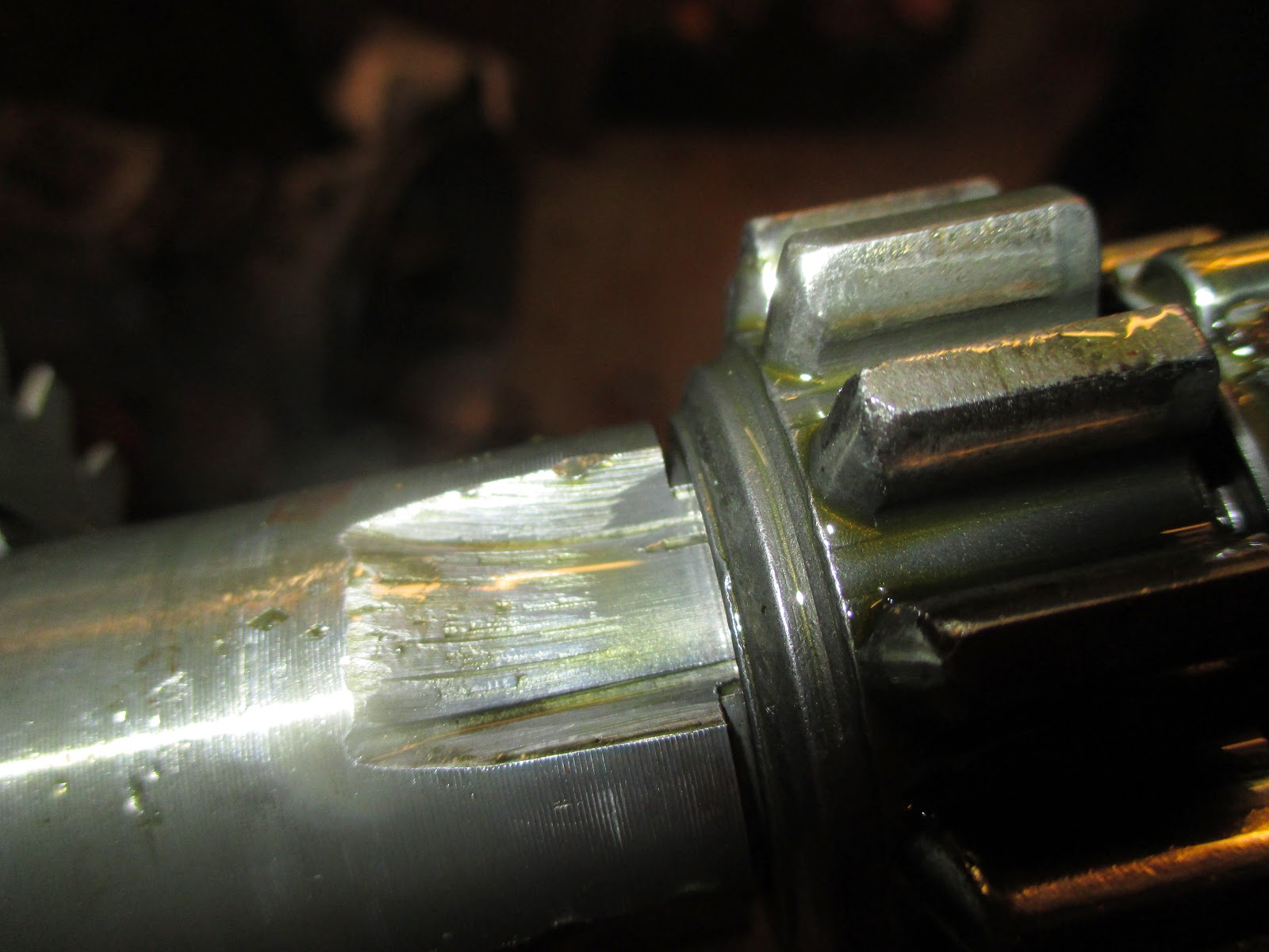
What we found didn't add up to the noise and lack of drive. Below you can see a damaged race for the rear layshaft bearing, in the next pic the gear is not fully seated on the layshaft.


     At the end of all this work we knew it must be something else. Someone(Mark) on a forum(GnR) had suggested it was the diff, but due to the noise coming from the gearbox I had discounted his response, Sorry man. So Brett pulled out the floor jack and jacked up the right rear wheel and tried to turn it, it wouldn't budge....sigh, all that work....
    Brett had to go as it was dark and he had a date, while I set about checking out my spare gearbox of unknown condition. I opend it up to find sludge inside so decided to take it apart and check it throughly, surely out of 2 boxes I could get 1 running!  Well the simple answer was no. By now it was 930pm and my back was tired and starting to hurt.

    I went inside and cooked dinner and sat down with ice on the back and watched a movie. The next morning I got up to find out what was wrong with that wheel, Brett and Linus were due up later(I thought to help, but not so as it turned out).
    True to form I couldn't make that wheel budge either, so thinking it could have been wheel bearing or diff I removed the wheel and pulled the inner axle. The hub still would not turn! With deeper investigation I found one of the springs broken on the brake pad and once I removed the pads the hub turned. I think that because of sitting for a month and in the rain it was frozen in place.


     So moving to the other side I pulled the wheel and then the inner axle, both axles showed minor wear and came out easily. Then it was on to the diff removal, dumping the oil out and with it came big chunks of metal from teeth........Mark was right.........
     Once out I could see that the ring/crown gear had lost teeth, the pinion gear was damaged but intact.


    I spent the afternoon disassembeling the diff and with Brett and Linus checking my spare diffs and acessing my options.
   As far as the diff goes I think this is the time to go with a locker and I am checking my options, I already have a set of 24 spline axles in the batting circle.
    For the mainbox I am going to replace the layshaft and rear layshaft bearing plus the 3-4 syncro, I bought a gearbox seal kit and I might hook up the reverse light.

   Oh, and my back well it still hurts after all the work each day but with ice I have been able to knock the pain down to a dull roar and some siatica on my right side, hopefully I can do another chiro and get that settled this week during the rain...

If I don't make back before then, have a happy Holiday!

Sunday, November 30, 2014

delayed by back injury

I hurt my back a couple of weeks ago and then redid my roof skin to some small avail.... I can't sit long enough at the computer to type up the update but will when I can.

Monday, November 10, 2014

Effing Land Rover, syncro spring broke

I am not happy, something broke in my main gearbox Saturday night.


syncro spring.

Monday, November 3, 2014

Land Rover windscreen leak, door latch fixed

It finally rained here in California, YAY!  I was able to go out during the start of a shower and find the leak causing the puddle on the drivers(left) floor mat.  I sat there for a few min and then it started, it was coming out under the retainer for the glass in several places. The worst offender was dripping onto the windscreen holddown and then onto the floor. Even when it was happening the clear water was hard to see.


While it was raining I tried pushing down with a putty knife the sealant on the outside of the glass but it helped not.. So I had to wait a couple of days for the rain to stop and things to dry up some.
Today was the day so looking at the outside seal I could see it was cracked and seemed too small a volume.


In my stuff from long ago I have some seal that was called Duct Seal by the guy who gave it to me. I have had it about 40 years in a bag. It is pliable, sticky, and works great. I set up myself with a hair drier and dried out the outside channel and heated up the duct seal then pressed it in with a putty knife.

Once pressed in I cleaned up the look with the putty knife so it would look better.

It took about a half and hour to work my way across the bottom and fill in the gap. Hope it stays!


The other thing getting done today was ever since I put my doors on the drivers door has needed a huge slamming to get the lock set so I could lock it with the key. I set out to figure out what was going on. I tried adjusting the stiker but nothing was working so I took it off and tried it in the latch. That is when I found that it wasn't fitting correctly but I couldn't see where the "jam" was. So I looked for witness marks, The rubber was hitting the side of the latch so I ground that down, no joy....
    Next I started taking measurements to see if the latch and the striker were a good fit. The latch seemed a bit tight so I got out the Dremel tool and smoothed out the lip, that helped a little but enough to let me know that something else was binding.
Something I couldn't see.........Then I found it one of the screws which holds the rubber on the striker was 1/32-1/16" of and inch too long. So I ground it flush with the Dremel and tried the striker in the latch by hand and VIOLA! It worked! Then I reinstalled the striker and it's all good now. Whew!

Thursday, October 30, 2014

Land Rover accelerator fix

So last week I was driving home over a hill, in front of me was a Prius going under the speed limit and I decided to pass. I gave it some Wellie and it charged up the hill but the Prius went faster too....I passed just at the crest of the hill and all of a sudden my accelerator pedal dropped to the floor!!! Lucky for me I had enough momentum over the top as there were around 5 cars behind me passing the Prius too.
    Coasting down the other side I had time to think, all I knew was I was in gear, the motor running, but no control of the engine speed. I decided to pull over on the first side street towards the base of the hill and not chance that I could make the left turn into the store parking lot.
   After pulling over and shutting down the motor I climbed out and looked at the pedal,,,,,it just lay there forlorn and disconnected from the cable. The piece of all thread I used to attach the clevis to the pedal had snapped above the locknut. It was only 10-32 and using the pedal flexed it too much.
   Out came the tools and the broken bit removed from the pedal, here is where I got lucky, I had left enough of the all thread in the clevis to effect a repair. Still I gingerly drove home.
   Usually I feel like I overbuild things but I had to go with the 10-32 due to the clevis threads.

   I slept on it that night and devised a fix. Using 1/2" steel rod that I had, I fashioned a replacement. Into one end I made a clevis using my angle grinder and a 1/8" cutoff wheel, thru that end I drilled a 3/16" hole for the clevis bolt.

On the other end I drilled and tapped it for a 1/4-28 thread. I had to also enlarge the hole in the pedal itself. Once all done and bolted in when I drove it the pedal was WAY too high even though I used the same measurement as the clevis. I drove it this way for a couple of days trying to figure out what to do.
    Again I do my best thinking prior to falling asleep, I needed to put a bend in the top of the rod to allow it to sit lower at rest.
    So I made another one slightly longer so I could cut it to final length, cut the clevis, drilled for the clevis bolt then heated it up to bend and the clevis bits folded up.......sigh.......
    Cut another piece of rod off and this time I heated it and bent it first! Then cut and drilled to make the end a clevis and the other end drilled and tapped for the 1/4-28 bolt.
    Turns out I didn't have to cut it shorter, fit great!


There was an unexpected plus from this, the throttle response is quicker as there is a more solid connection between the pedal and the pump.

Thursday, October 16, 2014

Land Rover fan shroud gets made

   I decided that while I was sourcing a Defender intake/exhaust/turbo for my Disco motor that I would make a fan shroud for the 19J motor. Thanks to Brett G. I realized that I could do it as I thought that the radiator had no mounting holes predrilled in it. My old eyes just couldn't see em...........but Brett could.
    Starting with some aluminum sheet I had I made measurements and laid out the size and put some bends in the body of the shroud. Next the body was temp mounted by the 2 top screws and a circle was drawn using the fan blade for the centering device. Then the circle cut out.


You can see that I couldn't just mount a stock shroud as my engine is offset for some reason.

    It took quite a bit of mounting, checking for fit, dismounting and pounding with a hammer to get the bend on the bottom to fit the bottom hose. Once the body was set with the hole I measured the side holes and drilled them for the mounting on 4" centers as indicated by the exhaust side of the radiator. This also fit with the drill pattern of the old radiator in my shed.
   A cowl was made to enclose the fan itself and clamped in place and marker holes drilled and then I put in 1/4-20 rivenuts to hold the cowl. again the body was temp fitted and the cowl fit checked, bummer, I had made it too long and had to trim the ends shorter to clear the alternator and the bottom hose.
 

How it looked on the body;


Once the cowl fit and the body ready the fun really started..............the holes on the battery side were not on 4' centers and due to my hammering on the bottom hose area the body had spread and the sides did not line up any longer. It took many fittings to square everything up and then find the holes were not correct.  *^$#@$#@!
    Those holes were measured and redrilled and in some cases Dremeled out oval. Now those screws are damn small, #6's, and my hands and forearms fat and if you have ever worked in there it is not condusive to tools either. But I got it on! Only to have to take it off again to make a top cover piece. The top cover has to have a relief in it to allow for the top hose. You can see it in the last pics. So it was cut and the top made and fitted and then reinstalled and the holes for the rivenuts predrilled then removed and the rivenuts installed and all was put back together and the fit checked for interferance.
    Once it was all OK I put on the top hose and fired it up. No weird noises and no leaks!!!


   All this work took me 2 days, about 5 hours just to make the body, I have no metal brake so I clamp everything to my welding table and bend it with a deadblow hammer, Using a jigsaw the shapes are cut out. It took about 6 hours to fettle the cowl and top piece and get the darn screw holes right, lots of bending over with my head under the bonnet.
    By now you might be asking yourself if it was worth it, I was, but I was too tired to take it for a drive. So what else could I do......I had a late lunch and took a nap! :^)

    Later I did take it for a quick drive, One of the roads around here climbs 2000ft in 3 miles, on the drive over to it the temp guage seemed a little cooler. I couldn't tell for sure as it's one of those numberless guages. The last time I test drove this hill it was 20F hotter outside, the temp guage seemed to get up to the red later but by the time I reached the top the needle was over halfway into the red.
    I have a small infrared thermometer, I don't know how accurate it is but it should be relative to itself, using it the head by the temp sender was 258F the top hose was 195 and the bottom hose 165, the oil cooler hoses showed a delta T of 45F.  Once home the head showed a 180F and the top hose @150 and the bottom 125. I don't remember the oil cooler temps. I have a 180F thermostat.

Now if I can only find those Defender bits........cheap.

Hey, Paul does this help with your fix? ;^)

Off Road lites and simple roof rack

Well a while ago in 2010 I bought some used off road lites, namely some Hella 2000's. When I ordered my wiring harness I ordered a circuit with a fused relay for roof top lites. I finally got around to deciding that I could put them on since I have the RTT.
    To do this I just moved one of the unused roof racks forward and after some experimentation I found a place and decided on a type of mount that I will see if I like enough to paint and keep. It all vibrates a bit when jiggled so I don't know....I've just used some superstrut and bolted it all together. I might weld it all up if I like it. I used the Gamiviti rack clamps; http://gamiviti.com/html/products_roofracks.html
  So on to the pics( I know you are dying to see..............)


So after driving with the lites so fitted it was found that they are too loose and the housing vibrated back and onto the roof. As I thought this was going to happen I was ready with a plan!

I made a roof rack to help with the vibration and although not quite finished (still to add plywood) it really stiffened up the front crossbar. It was made again with Superstrut cut and welded to make the roughly square 4x5 shape.

I then reengineered the lite mounts by using some 1/4 x 2" aluminum bar stock I had and made some flat, less tall mounts. The allen bolts I originally used for theft prevention were already rusting so I went with 3/8-24 2" stainless bolts and grade 5 nylock nuts. Whilst this quieted the vibration a lot I still had enough to worry about the light beam getting out of alignment. The Hellas came with some braces but I didn't get them from the PO, so I made my own. There is a local guy who buys and sell machine shop tools and he has scrap metal, from him I bought a piece of 13ga SS 5x12". I cut out 2-5"strips.


center punched them

drilled pilot holes

and the final 1/4" holes

at the same time bending and fitting as I went. These were bolted into the lite housing using the supplied holes;

The lites were re-installed and using a thick washer on the back side of the brace clamped to the rain gutter. I also added a roof rack mount to the center of the roof and the rack, I can walk on the rack with confidence that I won't bend anything on the lites.


With that the vibration ended and now it is solid!


You can see from the pics I need to get some flood lites next time, these spots allegedly reach out 750meters.

Headlights only;


Spots before all brackets were on.


So I have been asked for more detail.
Here is a picture of the top mount and how the lite bracket is bolted to it and it to the roof rack, you can see I've run the wiring inside the SuperStrut.


I split the wire in the strut for both lites and only ran a single wire from the relay.


I brought this wire back through the bulkhead and along the parcel tray where I tapped in for the idiot light. Here is the panel with the light switch on the left and the yellow idiot LED on.


The back of the panel looks like this( I like my wiring long so I can get in and do work):


From the relay the wire comes out the side of the parcel tray where it runs up next to the windscreen.


From there I ran it under the door seal and in the junction of the roof windscreen. Here you see it as the dark red wire.


On the outside I just ran it on the roof rack mount and tried to keep it from possibly getting snagged on branches with wire ties.


Then just along the inside of the rack where it splits for the 2 lites.


Ground is through the light case and the mounts.