Friday, November 16, 2012

109 seats

Ok this was the next thing to have to be redone. The fitting on the fuel tank sat too high to let the seatbase lid sit properly. I had to lower the fuel tank....both ends.... In a way it made things easier for the next time. I had 5/16" stainless steel bolts holding the tank in place. All I did was take the Nyloc nuts off and put new hex nuts, also stainless, on. Complete with washers this spaced it out enough. The benefit is that now the bolts are solid and only the nuts have to be removed to drop the tank.I never have to (I hope) get into that crazy little space to hold the rear bolt heads!
Now the lid will clear!
The bottom pics show the spacers added to the underside of the fuel tank. I found some Defender seats on Craigslist in nearby Carmel. Thanks, Mack! So after the seatbase was in I put in the passenger seat (RH).
Once mounted I got in to try it out. As I closed the door I found that it was too close to the door so it would have to be moved over. I ran it forward and back on the slide to see that that bit worked. When the seat was removed I noticed a scratch on the seat base. I thought I had done it when setting the seat in place. I moved the seat over and bolted it back in and again climbed aboard to check the fit. It was now far enough from the door and moved fore and aft easily. I then checked how the seat bottom came out and pulled it up. There I discovered another scratch in the seatbase paint. I knew I didn't do this one putting the seat in, so I started looking for the cause. It was the back edge of the bar used to unlock the slide. There wasn't enough clearance to let it slide...It is always something ain't it! So again I went to Fastenal and bought some thick 1/4"id stainless washers. They are 1/8" thick, so by stacking 2 in the front and 1 in the rear I was able to raise the seat enough to clear the base with the slide mechanism.
Next up I put on the radiator and filled it up with a 50-50 premixed brew. And guess what???? NO LEAKS!!!!
Then we had a slight rain and I found out my roof leaks. @#$%^&*(!!!! I couldn't tell that day where it was comming from but today it is raining once again and I know where now and have to wait for it to dry out before I can attempt to seal it.

Sunday, November 4, 2012

109 tub back on, rear step, indicator rebuild

Before I get to the tub story I want to tell you about; the 1960 Series 2 model came with a dash mounted switch for the turn signal indicators. The one I had was broken. The threaded part which attached it to the dash had broken and someone glued it back on and if fell apart. My friend, Linus, had one that wouldn't turn so I decied to take the 2 of them apart and make 1 that worked. The pics show some of the insides all corroded up and the finished switch which I hope will work.
Two weeks ago Linus came up and with the help of a neighbor(Joe) we took the roof and tub off. Then I set about to rectify the issue with the frame fit. Taking measurements from the frame and comparing them to the book showed some discrepancies. What I think may have happened was the PO had backed into a log at some point. this had crumpled the right rear corner, body and crossmember. When I made the jig to reset the new crossmember for welding, I just used the old crossmember as the template. It must have been bent. I just figured it was OK and didn't measure anything back then. Plus the fact that when I got the frame back from the galvanizers I had to straighten up the rear and front body mounting tabs as they were askew. I was also concerned that the bending of the bulkhead might be an issue. Anyhow it's my best guess as to why it didn't fit. So I spent a day cutting and grinding the old welds off, gratefull that I had just sleeved the frame rail instead of splicing onto it. Then after copious measuring and clamping I felt the rear crossmember was in the right place.
The nearest measurement would have been the 18 1/8in from the centerline of the rear spring hanger bolt to the back edge of the crossmember. I found it too difficult to find the cl and my 109 had different measurements than Linus's 109. Then I decided to use the overall length measuremant 166 63/64in. While going with a tape measure under the bulkhead I could get a straight shot on the LH side, but the fuel tank was in the way on the RH side..... Looking at the book I could use the measurement from the front of the outrigger, which has the body tabs, to the rear of the rear crossmember 81 1/2in. This also had the correct distance for the tabs to fit under the body. The next day I welded the frame back together. I took no pics.... I did spray with cold galvy and cover with spray-on bedliner to help seal and protect. Waiting a week, Linus came back and with the help of another neighbor(Bob) we put the tub and roof back on one Tuesday evening.
As you can see from the photos I worked into the night to bolt on the tub and roof. Since rain was coming the next day I went ahead and put on the doors. The doors were hung loosely without the seals in place. Even this way the light rain was kept out of the body. It wasn't until after the rains ended that I was able to install the seals. With the seal inplace the doors would once again not close,...AARRGGHHH!!!! So I took some measurements for the door openings. Sure enough it was 1/4in too narrow at the top of the bulkhead. At this point I removed both the steering support brackets. On these I wallowed out the holes so that I could tilt the bulkhead forward. Taking a piece of 1/2in square tubing I made a piece 1/8in longer than the (stock)opening and wedged it in between the bulkhead and the tub right at the top of the bend in the body by the top hinge. This pivioted the bulkhead on the frame mounting bolts. Next I installed the steering support bracket on the side I had braced and tightened the fittings up, then moved over to the opposite side and repeated the process. After doing both sides I reinstalled the door seals and Lo and Behold the doors shut!!!! Next day I bolted down the front body tabs, hooked up the rear wiring and installed my new rear step. A couple of weeks ago I was at a stop light and next to a fire truck when I looked over at it and saw what appeared to be a folding step. At my next opportunity I went to the local Fire Dept to see if I could find a brand name or part number and see how it was mounted. They had them on but no name or number to be found. So since Google is a close friend of mine I asked it to search for a fire truck folding step. It came up with a couple of options. I bought this one; http://www.worktruck-outfitters.com/folding-foot-steps-trucks-galvanized-p-3722.html Mainly because it is galvanized and "fits" with the overall look of my rig. The local Ace hardware store supplied the grade 5 4x5/16 bolts. I marked and drilled thru the crossmember and thru bolted for strength and security. In one of the photos you can see my size 8.5EEE's for a size comparison. The step mounts up above the bottom of the rear crossmember and will be less prone to damage or dragging. It has a stainless steel spring system which holds it in place either up or down.
So since the doors close I put in the seat base. Here I ran out of stainless washers so the floor and seat covers are just laid in place for now.
I was able to find a purchase some Defender front seat on Craigslist and those are waiting(in my living room) to be installed. Meantime I am working on the steering column modifications.

Saturday, October 27, 2012

tub time!

I got the roof and tub off last week and spent the last 2 days cutting off my old welds for the rear crossmember, then lining up the same in the correct position. I wound up using the overall length 166 63/64in dimension. It was too difficult to try to go off the centerline of the rear spring hanger bolt hole(18 1/8). I also went off the outriggers which hold the tabs for the rear tub(81 1/2in) because the fuel tank was in the way for getting the overall length on that side. I also made sure that the tub measurement for the tabs was correct for where my new location was. Then I welded it up. Somewhere in the welding process the string I had attached to the wires got burned thru. Good thing it wasn't the wires! Hey I did something right for once! Since the string was in the frame rail I had a dickens of a time getting the wires back out. I fnally resorted to making a hook out of brazing wire and catching the knot holding the string onto the wire. I still have to finish it off the bottom side has a couple of holes I need to reweld. Then I will clean it up with a wire wheel and spray cold galvy (93% zinc) over the area and then cover that with spray on bed liner. That should add corrosion help(zinc) and a barrier for mosisture penetration(bedliner). Next will be to scrounge 3 people to put the tub and roof back on before it rains again.

Wednesday, October 17, 2012

109 rear crossmember issue

I looked it over in my mind and asked friends what to do about the rear crossmember. I've decided to..........cut my welds and reweld it on. Then cover it with cold galvanizing spray and coat that with spray-on bed liner. I'm going to have to unbolt the bed and roof and move it up so I can get in with tools and welder. I'll let you know how it goes!!:^)

Thursday, October 11, 2012

Land Rover power steering on 109

When we last left out intrepid rebuild I had just run up against the exhaust steering box interferance problem.
I admit it bummed me out. I took a week just trying to sort out my options after my dissappointment was gone. I had called the local muffler shop and 2 guys were going to come out the next Tuesday to see if I cut the exhaust manifold shorter so that they could make a downpipe for it. So I went to fiddling with making the holes for the top oil cooler brackets to bolt to, and putting in the seat base.
I got the seat base in position and bolted up the rear edge. Then I installed the door sill plates. They didn't just bolt on though, the 90 degree angle on the upright was too far away to fit so I had to loosen the bolts and tilt it forward. My first indication something wasn't right. Once that was done I looked at the seat base sill holes they didn't line up either??? Over the weekend Brian H. let me know he had some old LRO magazines to get rid of. So I went up to Half Moon Bay to say hi and collect them. While visiting I mentioned my issue with the steering and we discussed options. By that time pending what the muffler guys were going to say my best option was power steering. I was leaning in that direction. Brian said If I wanted to do power steering I could have the parts he'd bought to put power steering in Gonzo before he decided to do the overhaul of Gonzo. He had the Saginaw box and canned ham pump and some of the steering column connecter bits. Of course I said YES!!!
I brought those home with the magazines on my motorcycle. Then I started studying up on the conversion reading TeriAnn's website http://www.expeditionlandrover.info/ about the options. Tuesday I picked up some 1/2in plate and started making the mounting bracket. That evening the muffler guys came over and said yes to my idea of shortening the exhaust manifold. By then I had decided on the power steering. That following weekend was the Sunday that I went to Hollister with Brian H. and Gonzo. After seeing the PS work on the 2 different Rovers and checkng out the Saginaw vs the ZF box(p38 Range Rover) I further decided on using the ZF. This was partly due to Timm saying he'd broken 2 of the Saginaw's while attempting tight turns. Partly due to my motor had the PS pump bracket and I would have to fab up a bracket for the canned ham.
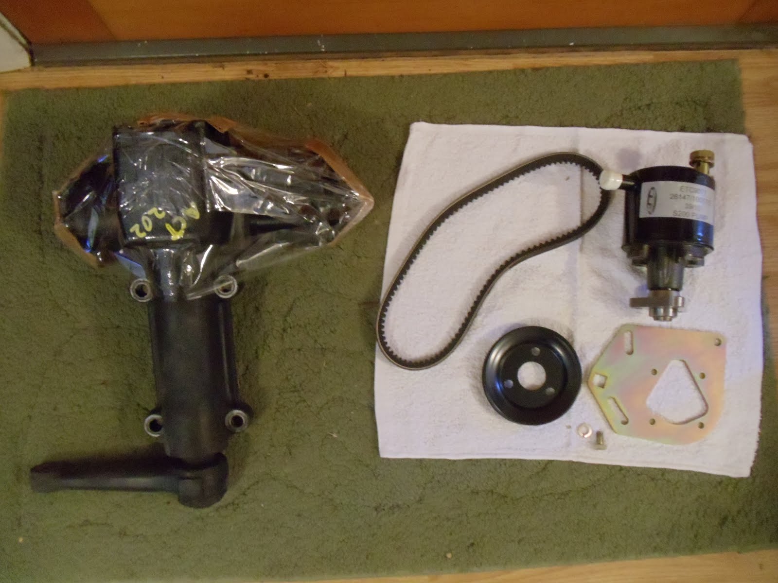
So off to the internet, I ordered pump, pulley, belt, tensioning bracket from Craddocks in the UK and found a ZF box on EBay for $75+ shipping($112total). I have yet to get a resevoir and PS oil cooler and connecting shaft to the column. I am getting some from a D1 from guys on line.
Then I went to Michigan a couple of weeks ago and helped a friend drive his 2 cars back to Santa Cruz. All told it took a week to fly out and finish packing and drive 2330 miles. Once I was home I started on mounting the steering box. I got 2 pieces of steel 6x7x1/2 I used a center punch and marked out the holes and drilled them out with both plates clamped together. 2 birds with ones stone, right? Well one of the holes was off center on both plates. I couldn't get the bolts in!!!!!!!! Of course that was on a Friday.......... Over the weekend the weather forcast was for rain on Tuesday so I set about putting on the front doors. I got the right hand door on the hinges and went to close it but it was too large for the opening. WTF??? After some head scratching I figured that I had somehow mounted the tub about a half inch too far forward, hence the mismatch with the door, seatbase holes and door sills. So If you remember I had to replace the rear crossmember due to damage and rust issues. I made a jig off the orginal rear tabs and used them for the new crossmember. After checking the book frame dimensions I figured that I was 1/2 inch too far forward *&^$&*%$&*(!!! that was last Sunday. I was stunned and bummed to say the least. Monday I got 2 more plates this time 5x7x1/2 the same size as Timm uses. I was more carefull to layout the holes what I did was put the box on my worktable and support the pitman arm end so I could easily get under to the flat "mounting" side.
Then I carefully located my bracket underneath and using vise grips I clamped it by 2 opposing holes. Next I put a 31/64th drill bit in my drill and inserted it in the holes and drilled into the plate. This bit was the largest I could fit through the hole without making it bigger. The point on the 31/64th made a center mark for the hole location.
I did 2 opposing holes and then shifted the clamps and marked the other opposing holes. Once I unclamped the plate I could take it to the drill press. The centers turned out to be 80mm on the horizontal and 135mm on the vertical. Now on the drill press I started with 1/8th and worked my way up to 27/64th for the top holes, this is the size for tapping. For the bottom holes I kept them at about 3/8ths.
I had decided to use 12mm bolts and secured a 12x1.75 tap and 4 grade 10.9 bolts. Using the tap I did the 2 top holes, leaving the 2 bottom holes alone. 
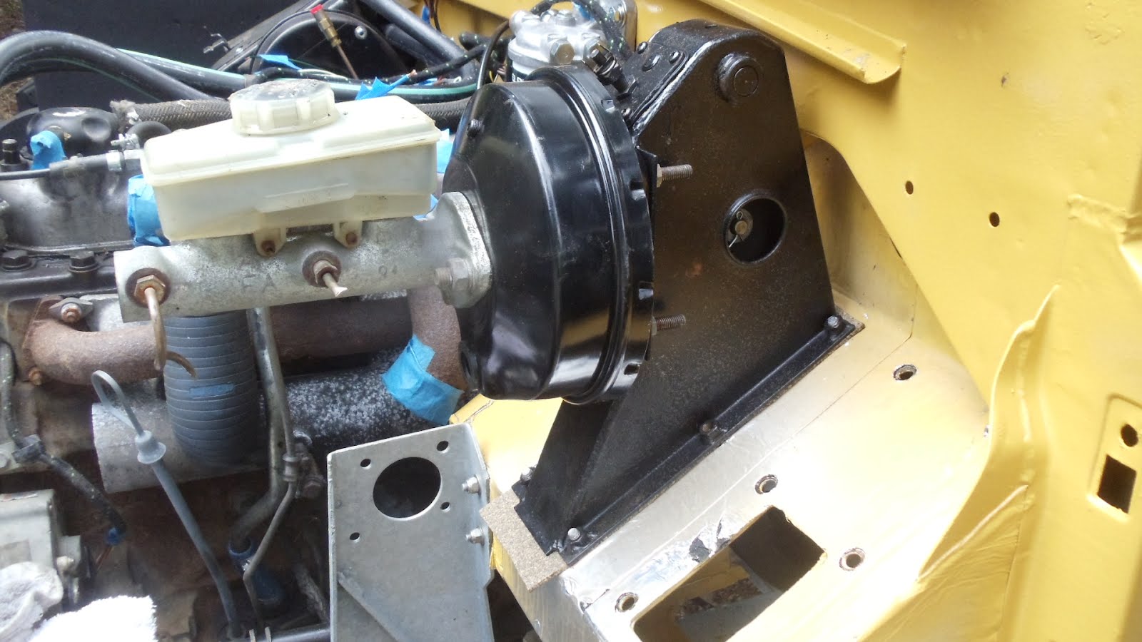
Taking the partly finished plate to the chassis I clamped it firmly in place and mounted the box by the top bolts. This way I could adjust the height and tilt of the box before welding.
I used a tie rod end mocked up in the pitman arm to check for clearance under the frame, I wound up with around 9/16 clearance. I hope it is enough!
The next step was remove the box and weld in the plate. I know my welds look like corn cobbs..... Once the welding was done I sprayed it with cold galvinizing. Then I proceeded to drill out the 2 bottom holes to tapping size and then tapped them.
Odd thing the cutting fluid removed some of the cold galvy so I had to respray. After it was dry I went ahead and mounted the ZF steering box. Here I realized that in the straight ahead position, ala the orginal steering relay, that the pitman arm moved further to the left than to the right. After playing around with it and a call to Timm C. I discovered there is a pointer on the input shaft and a notch on the box body designating the center of lock to lock. This leaves the pitman arm to the left of the frame rail.
I went on to start mounting the oil cooler so I could figure out where I needed to modify it to accomodate the box. As I was starting that I realized that now would be the best time to install the pump as nothing was in the way, so that took place.
Linus came over and we talked Rover stuff and went to dinner. There we discussed where to go this year at Death Valley. Today I finished up the oil cooler install but see that I need to make one more change to the clearance around the box. I am using 2in 1/4x28 SS bolts and nylon bushings as spacers for the top of the oil cooler bracket. All this while dodging the thunder storms today.
So I am unsure what to do about the tub. The easy way would be to unbolt the tub and lift it over the mounting tabs and make spacers to bolt it up with. The right way would be to cut my welds and move the crossmember back the 1/2in. The bad part about this is the frame is galvanized and I would be opening up a section on each rail for rust. I just started to look at it and measure stuff late today. What I think happened was the PO had backed into a log and bent the right side crossmember outrigger, among other things. When I made the jig I just fitted it to the central tabs on the frame and bolted the new one up thinking nothing was wrong. I should have measured! It looks like if I took out the plastic spacer/corrosion blockers between the tub and tab I could gain 3/16ths of an inch. Moving up to the passenger door I tried to see how much I needed to go to fit the door. Once I started fiddling with it I could see that the Defender weather stripping was interfering at one spot at the capping level so I removed the 1/4in bit in the way. This got the door partly in the opening. Next up I got out my deadblow hammer and proceded to put the weather stripping on as tightly as I could. Lo and behold the door went on! As it was getting dark I quit for the day and came inside for dinner. Maybe I won't have to move the tub after all! Not going to hold my breath though ;^) Before I left for Michigan I had a local welder make some stainless steel mirror arms. He welded 3/8ths bolts to 1/2in rod and bent it like the stock ones, I had them made 2in longer than stock.

Friday, August 10, 2012

Land Rover headache #109

If you remember I posted about(I think) the fit for the new Series 3 brake tower. I was awaiting pics or some further info on whether or not I had to enlarge the slot the pedal goes thru the bulkhead. Well, the other day Brian H. came to show me his refurbished Series 3 88 Gonzo. I got a good look at the pedal slot and knew what I had to do.
So next was just a simple matter of marking out the lines to cut, drilling holes at the corners and using my jigsaw cutting out the necessary metal to enlarge the slot.
WHOA NELLY!!! Did I say simple? Oh I had to make the top cut from inside the footwell...the stiffening bracket was in the way. When I went to put the brake tower on the stiffening bracket was STILL in the way! So I had to cut it off. Now I hated cutting into my galvanized bulkhead, 'cause I know that's where the rust will start.
Then I had to find and clean out the holes for both the brake and clutch towers. I could find them by pressing with my fingers and leaving a depression. I used a circular wood gouge I have to cut a nice hole around the hole thru the soundproofing.
So then I could fit the brake tower.
Which all brings us to today! I went out to fit the steering column. wouldn't slip right in. First I had to remove the brake tower. Then I got it in position and went to put on the stiffener. Well it wouldn't fit the exhaust is in the way!So I took it out and ground it down so it would fit.
But that' is not the only thing, it looks like the steering rocker shaft and drop arm will be in the way of the exhaust down pipe. Am I having good luck or what???
Then I had to do some fiddleing around to get the brake tower to fit around the steering box. This took several remove and grind off bits until I got it to fit. Once that was done I tightened up the bolt to the steering box to see just how bad the interferance is with the exhaust and by then it was too hot to work out there any longer today.