Sourced some new o-rings from The Hose Shop (Thanks again Linus!) It is up and running with no fuel leaks!!
Now I wait on mirrors........

Monday, June 17, 2013
Sunday, June 16, 2013
109 disc brakes
Well,
I finally figured out what was wrong with my disc brakes. It seems that the front calipers were on the wrong sides. I noticed while bleeding them that the bleeder was on the bottom. An email to Timm Cooper confirmed my guess. So yesterday (Saturday) I swapped them, bled them and bingo-bango-bongo I had brakes! I check my photos and could tell that the wrong one was put on when ROAM was here to photograph the installation of the conversion kit. I couldn't tell you who did it though. Probably me........
So of couse I had to drive it around the neighborhood,,,,,But I succumbed to temptation and took it out on the road. Now I live in a rural mountain valley so I had to drive on one of the main roads. I was just going to go 2 miles up and turn around and come back. Drove about a mile when I looked at the dash and saw the charge lamp on.......thinking I had alternator or fan belt issues.............
Still drove to the turnaround spot as there aint much else around. Then came back home. I have no rearview mirror which was uncomfortable but I made it. The turn signals worked fine as do the brake lights.
The ride was fairly soft, must be the 40psi in the tyres, power steering worked but seemed to need constant correcting. Even though it is a 109 it has more power than my 88 2.25 diesel.
Once home I went about checking the charging system. Turns out I had wired the lamp into a constant power circuit. I changed it to an ignition power circuit (as in the diagrahm) and the lamp went out.
Today I tried to fix the leaking diaphram on the bottom of the injector pump. Well it's not the diaphram but the o-rings for it. Couldn't find the correct o-rings or crush washer. Will try some places in Santa Cruz tomorrow before I decide to travel the 2 hours up to Oakland.
Here's a link to my first test drive when I found out the brakes were not so good; http://www.youtube.com/watch?v=4zzW35OFohw
Tuesday, June 11, 2013
Land Rover axle breathers
G.day, I bought a breather kit from Robin on the Series 2 forum. This includes all the bits for both axles and the transfer (xfer) case and over drive (OD). I had to also purchase a tap for the top of the OD and xfer cases. Online I found one from Ebay. A 1/8 BSP size is required.
Starting at the rear I pulled the axle breather out and put in the new one then slid in the end of the hose. I ran the hose along the brake pipe securing it with the zip ties provided. I made sure to leave slack for the axle movement. Then it was run up the inside of the RH frame to under the seats. Here I put in a provided "tee". Pulling off the top of the xfer and OD I drilled and tapped the xfer plate. On the OD there is already a breather hole with a cotter pin to keep it unpluged. Once the pin was removed I drilled and tapped it. On the inside of the OD plate is a splash plate to prevent oil from exiting the pin hole.
Soon the xfer plate was reinstalled with a new cork gasket and the breather hooked up. The OD plate was next, #$% no matter how I tried the $%^&*thing wouldn't fit under the handbrake cross shaft...................
So being the resourcefull fabricator I is. I flattened a piece of copper pipe and clamped it on the underside of the hole in the plate. Now I could weld it up as the weld won't stick to the copper. Now that that was done a new hole was drilled and tapped 3/8" away from the old hole but still inside the splash plate.
Back at the 109 the plate was installed the breather hooked up by a tee to the xfer case and then to the tee at the frame. All the while using the provided zip ties and securing things from vibration.
For right now I just have the bight run up the RH side of the bulkhead, around the heater (staying away from heat) and I have a small filter on the end of it.
Pics are of the breather kit and xfer case--OD plumbing.


Acouple of weeks ago I put insurance on my 109 as I felt it was a) to valuable to not have insured and b) getting close to being drivable. I also mad an appointment at the California Department of Motor Vehicles www. DMV.Ca.gov
DMV was yesterday so now I am legal to drive it on the road.!!!!!!!!!!!!!!!
I am still having brake issues as if there is no pressure when the motor is on. The brakes work when pumped but it's not good enough for me to take out on the road. Hopefully I can find someone to help me re-bleed them and see if there is more air.
I'll leave you with some pics first is the winch, I wound the rope on today with only 1 major mishap. The snap ring holding the brake drum came off while winding on the rope. I got it all back on but will it stay??

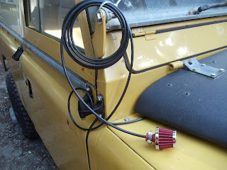
Second it the top of the breather kit, I'm hoping to hook it to a snorkel.
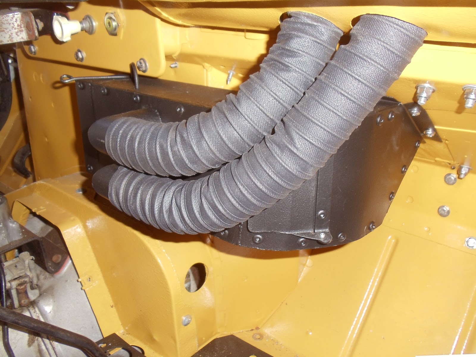
Third, I realized I hadn't shown the finished air distribution box. Not entirely pleased with it. The lower hose interfers with the door for the passenger, but it comes off easily and I don't have anyone riding there anyway. I bought part #5266K84--flexible duct hose, for dust 1-1/2"ID, 1-3/4"OD from McMaster-Carr. Your size may vary due to whether you want the hose inside or outside.
UPDATE 29 Sep 2021;
Starting at the rear I pulled the axle breather out and put in the new one then slid in the end of the hose. I ran the hose along the brake pipe securing it with the zip ties provided. I made sure to leave slack for the axle movement. Then it was run up the inside of the RH frame to under the seats. Here I put in a provided "tee". Pulling off the top of the xfer and OD I drilled and tapped the xfer plate. On the OD there is already a breather hole with a cotter pin to keep it unpluged. Once the pin was removed I drilled and tapped it. On the inside of the OD plate is a splash plate to prevent oil from exiting the pin hole.
Soon the xfer plate was reinstalled with a new cork gasket and the breather hooked up. The OD plate was next, #$% no matter how I tried the $%^&*thing wouldn't fit under the handbrake cross shaft...................
So being the resourcefull fabricator I is. I flattened a piece of copper pipe and clamped it on the underside of the hole in the plate. Now I could weld it up as the weld won't stick to the copper. Now that that was done a new hole was drilled and tapped 3/8" away from the old hole but still inside the splash plate.
Back at the 109 the plate was installed the breather hooked up by a tee to the xfer case and then to the tee at the frame. All the while using the provided zip ties and securing things from vibration.
For right now I just have the bight run up the RH side of the bulkhead, around the heater (staying away from heat) and I have a small filter on the end of it.
Pics are of the breather kit and xfer case--OD plumbing.


Acouple of weeks ago I put insurance on my 109 as I felt it was a) to valuable to not have insured and b) getting close to being drivable. I also mad an appointment at the California Department of Motor Vehicles www. DMV.Ca.gov
DMV was yesterday so now I am legal to drive it on the road.!!!!!!!!!!!!!!!
I am still having brake issues as if there is no pressure when the motor is on. The brakes work when pumped but it's not good enough for me to take out on the road. Hopefully I can find someone to help me re-bleed them and see if there is more air.
I'll leave you with some pics first is the winch, I wound the rope on today with only 1 major mishap. The snap ring holding the brake drum came off while winding on the rope. I got it all back on but will it stay??

Second it the top of the breather kit, I'm hoping to hook it to a snorkel.

Third, I realized I hadn't shown the finished air distribution box. Not entirely pleased with it. The lower hose interfers with the door for the passenger, but it comes off easily and I don't have anyone riding there anyway. I bought part #5266K84--flexible duct hose, for dust 1-1/2"ID, 1-3/4"OD from McMaster-Carr. Your size may vary due to whether you want the hose inside or outside.
UPDATE 29 Sep 2021;
How I fixed the door issue; https://poppageno.blogspot.com/2021/09/land-rover-109-heater-distribution-box.html

109 Land Rover, door latches, cards, seat belt lower mounts
Gosh, Where to start?......... The door latches and locks came in last week but they only sent me a 2 lock set keyed alike. I'd asked for 3. Not worth sending back so I re-ordered.
Mean time whilst waiting I went ahead and fitted the latches. The rear door was easy and the LH not too bad but the RH was quite abit of trouble. Mostly the drilling of the hole for the lock to poke thru the door skin. Really tough to center up properly. The hole is a 15/16" so I obtained a 7/8" hole saw and using my dremel tool sanded out the hole to fit the lock seal. The front doors are a ugly fit with the lock not centering once the latch was installed and fitted to the striker plate.


I also fitted the Iron Goat www.IG4x4.com door cards. I haven't put them on yet thinking I might have to take them off when I put on the locks. It took some fettling around the hinge bolts and the door limiter. I took care of this with my dremel tool. The holes for the hinge bolts I used my wood boring bits in my drill press to remove the preformed indentations.
 Here the LH card is fitted and below you can see the difference between the new and fitted cards.

 Above the RH card is fitted. It must have been a door made on a Friday! nothing lined up on it! I kept having to oval out the holes to fit the hinge bolts. The latch won't just slide on, I had to oval the holes to make it fit the striker.

The 8274 Warn winch needed some wiring so after some research A couple of lengths of #2 wire 36" long and eye terminals were purchased from my FLAPS, Boulder Creek Auto. I took this home and had to figure out a way to make a good crimp as my crimping tool wasn't large enough to do the job. So using the v cuts in my vise to hold small round objects, the wire and terminals were inserted. Behind them I put a 1/4" rod and smashed the heck out of them with the vise. Worked like Robert being my relative ;^)


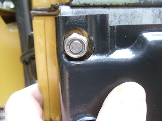
The bottom seatbelt brackets came the other day so those were installed. I used 1/4-28 stainless bolts. Fittment is pretty straightforward. Put in 2 of the bolts to hold the bracket in place and then drill the third hole and bolt it up. Series of pics show the process;


I went out a couple of days ago to start up the motor. I hadn't left the battery connected until after I had the first test drive. So now the battery was low, not enough to start up. I put it on the charger and it took a day to recharge. The next morning I went out with my multimeter and a test lamp to find the draw. By taking off the winch cables I eliminated that. Then using the amp part of the meter I removed the (+) positive terminal and measured the amps going from the + terminal on the battery to the + cable. I had a 44 amp draw. Next I began removing leads from the fusebox and leaving them off until the draw went away.
Thru this elimination process I found it was one of 2 green wires coming from the fuse box. Since they went into the bulkhead and were behind the dash I had to pull the dash apart(AGAIN!). This made easier by a cordless screwdriver ;^) Of course the green wire went behind my auxillary dash.........so off it came. The wire traced back to the water temp guage and the transmitter coming from the head. I had spliced it into a "always on" green wire leading to the wiper circuit. I switched the splice to a white wire connected to the keyed on circuit for the voltmeter.
Another check at the + end of the battery showed no draw.!!! I did something right!
Mean time whilst waiting I went ahead and fitted the latches. The rear door was easy and the LH not too bad but the RH was quite abit of trouble. Mostly the drilling of the hole for the lock to poke thru the door skin. Really tough to center up properly. The hole is a 15/16" so I obtained a 7/8" hole saw and using my dremel tool sanded out the hole to fit the lock seal. The front doors are a ugly fit with the lock not centering once the latch was installed and fitted to the striker plate.


I also fitted the Iron Goat www.IG4x4.com door cards. I haven't put them on yet thinking I might have to take them off when I put on the locks. It took some fettling around the hinge bolts and the door limiter. I took care of this with my dremel tool. The holes for the hinge bolts I used my wood boring bits in my drill press to remove the preformed indentations.


The 8274 Warn winch needed some wiring so after some research A couple of lengths of #2 wire 36" long and eye terminals were purchased from my FLAPS, Boulder Creek Auto. I took this home and had to figure out a way to make a good crimp as my crimping tool wasn't large enough to do the job. So using the v cuts in my vise to hold small round objects, the wire and terminals were inserted. Behind them I put a 1/4" rod and smashed the heck out of them with the vise. Worked like Robert being my relative ;^)


The bottom seatbelt brackets came the other day so those were installed. I used 1/4-28 stainless bolts. Fittment is pretty straightforward. Put in 2 of the bolts to hold the bracket in place and then drill the third hole and bolt it up. Series of pics show the process;


I went out a couple of days ago to start up the motor. I hadn't left the battery connected until after I had the first test drive. So now the battery was low, not enough to start up. I put it on the charger and it took a day to recharge. The next morning I went out with my multimeter and a test lamp to find the draw. By taking off the winch cables I eliminated that. Then using the amp part of the meter I removed the (+) positive terminal and measured the amps going from the + terminal on the battery to the + cable. I had a 44 amp draw. Next I began removing leads from the fusebox and leaving them off until the draw went away.
Thru this elimination process I found it was one of 2 green wires coming from the fuse box. Since they went into the bulkhead and were behind the dash I had to pull the dash apart(AGAIN!). This made easier by a cordless screwdriver ;^) Of course the green wire went behind my auxillary dash.........so off it came. The wire traced back to the water temp guage and the transmitter coming from the head. I had spliced it into a "always on" green wire leading to the wiper circuit. I switched the splice to a white wire connected to the keyed on circuit for the voltmeter.
Another check at the + end of the battery showed no draw.!!! I did something right!
Monday, June 3, 2013
Land Rover seat belts, oil/fuel guage, mudshield
Well I waited for the paint to dry and put in the reel mounts for the inertia seat belts. I was waiting for the bottom brackets to come in and after a couple of weeks I started to look and see who I ordered them and the door locks from. I found that I hadn't placed the order anywhere. So here is what the top bracket that I came up with looks like. I was happy that I had managed to keep the reel itself from taking up room in the usefull area of the interior.

 I then set about installing the seatbelt stalk, where the harness clips into. After some looking online I decided to make some spreader plates and bolt them to the lip of the bulkhead.

 In the mean time I've been working on the wiring, slowly sorting it out. I decided that my 30amp ammeter that was stock in the multi guage wasn't up to the 45amp on the 2.5 motor. After some more online research I found an oil pressure guage that would fit in the multi guage. This was sourced from John Richards Surplus in the UK. www.johnrichardssurplus.co.uk I needed an adapter at the oil pressure switch which came from Speedograph Richfield Ltd also in the UK. www.speedographrichfield.co.uk The hose and fitting came from The Hose Shop in Santa Cruz, CA. It took some fettling to get the guage to fit in the multi guage as it has a different(wider) shape. I was lucky enough to find a hole behind the hand throttle to route the hose and I used a grommet to blank it off.


Once the pressure guage was in and the air distribution box I could put on the RH wing. I did this with 1/4-28 stainless bolts. One thing I have gotten to use a lot lately has been my cordless drill. I cut off the handle from a 7/16 nut driver and chuck it into the cordless. Makes quick work of the installing of bolts!

 Installing the wing had it's own issues mainly the mudshield had to be installed and the hose for the heater intake. Well of course I didn't quite have the hole in the mudshield in the right place. So it was off and on with it a few times while using my nibbling tool to make it big enough to fit the hose. I picked up thermo ducting hose with fabric from The Hose Shop. Once the hose was connected at the blower end I could connect it at the intake end located next to the radiator support panel. The screen I used for this is 1/4" mesh stainless, I had put riv-nuts to the hose adapter and it is all held to the wing with 10-32 screws. I made straps to hold the hose up under the wing out of "Band-it" stainless steel straping, bolted(again riv-nuts) and screwed to the wing.
With the guage done I could also close up the dash. After doing so I connected the battery and turned on the power with the key. It was then that I noticed that the fuel guage was reading MT. I knew there was some fuel in it but not how much. So in went another 2.5gals. No change on the guage. :^(
So I opened up the seat cover for the fuel tank. I went about testing the wires for power thinking there was none. When I touched the hot lead with a grounded jumper the needle about slammed itself thru the roof of the guage! Well I had power alright! Now the needle was stuck on the top and nothing I did would make it come down.
AAhhh, I had a spare so I once again opened the dash and changed the fuel guage out. Nothing I did could make it read correctly. So I asked on the Series 2 Club forum for help.
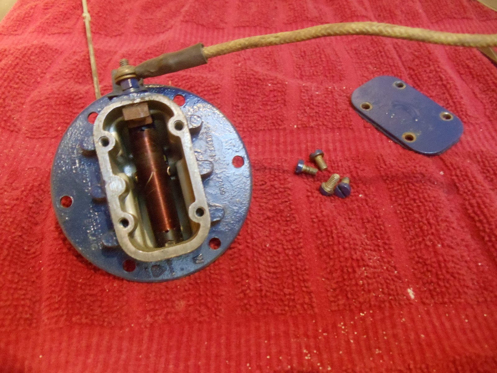
Turns out there are 2 types of guages and 2 types of senders, early and late, and they don't mix. Early guages have the arrow style needles and go with the domed senders(2 terminals for diesels). The late have the straight needle, need a voltage stabilizer and go with the flat top senders(3 terminals for diesel/ground). The second terminal on the early guages runs a low fuel warning light for diesels.
Now I had kept my orginal sender and had cleaned it up. Even though it is for petrol I can use it in my diesel tank with out the low fuel warning light.


 The bottom pic is the new generic "late" style.
While doing all this I realized that my fuel guage was "on" every time I hooked up the battery cable. It was a matter of disconnecting the wire from the fusebox and tapping into an existing hot when keyed circuit. When the sender and wire were swapped out and working correctly I closed up the dash!
A few days ago I put on the steering wheel, sorted out the positions of the horn and turn signal. Started it up and put it in gear. HORRIBLE grinding in the tranny. Traced it down to the overdrive, it is not adjusted right and not going into regular gear. When in od I could lift the clutch and move it forward about 6 inches and roll back on the chock.
I didn't drive it because I was still awaiting a new brake master cylinder. Well that came in on Thursday from LRSeries. www.LRSeries .co.uk But I was fighting with a clogged septic line starting on Wed night. Finally got it cleared Friday afternoon,,,whew!!
Saturday June 1st I put it on in the morning and used my power bleeder to bleed the brakes. Then I spent the HOT afternoon lounging in my daughters kiddie pool.
 Today was spent doing some of the little bits. I needed to attach the bottoms of my mudshields. I knew I wanted to space them away from the footwell, already purchased were 6 3/4x3/4" aluminum spacers. I had put these on my 88 and in doing so knew it was a tedious job trying to hold all the bits in place under the footwell and trying to stick a bolt thru from the inside.
My solution; I used super glue (Locktite) to glue the washers to the spacers, one on each end.


Once the bits were stuck together it was easy to hold them and put the bolt thru. This should help drop the water and dirt thru the footwell area and prevent more rust issues.


A happy owner!

Update; the superglue didn't work. It held fine for the original mounting but upon the first dismount it fell apart.


 |
| Back of guage |

Once the pressure guage was in and the air distribution box I could put on the RH wing. I did this with 1/4-28 stainless bolts. One thing I have gotten to use a lot lately has been my cordless drill. I cut off the handle from a 7/16 nut driver and chuck it into the cordless. Makes quick work of the installing of bolts!


With the guage done I could also close up the dash. After doing so I connected the battery and turned on the power with the key. It was then that I noticed that the fuel guage was reading MT. I knew there was some fuel in it but not how much. So in went another 2.5gals. No change on the guage. :^(
So I opened up the seat cover for the fuel tank. I went about testing the wires for power thinking there was none. When I touched the hot lead with a grounded jumper the needle about slammed itself thru the roof of the guage! Well I had power alright! Now the needle was stuck on the top and nothing I did would make it come down.
AAhhh, I had a spare so I once again opened the dash and changed the fuel guage out. Nothing I did could make it read correctly. So I asked on the Series 2 Club forum for help.
Turns out there are 2 types of guages and 2 types of senders, early and late, and they don't mix. Early guages have the arrow style needles and go with the domed senders(2 terminals for diesels). The late have the straight needle, need a voltage stabilizer and go with the flat top senders(3 terminals for diesel/ground). The second terminal on the early guages runs a low fuel warning light for diesels.
Now I had kept my orginal sender and had cleaned it up. Even though it is for petrol I can use it in my diesel tank with out the low fuel warning light.


While doing all this I realized that my fuel guage was "on" every time I hooked up the battery cable. It was a matter of disconnecting the wire from the fusebox and tapping into an existing hot when keyed circuit. When the sender and wire were swapped out and working correctly I closed up the dash!
A few days ago I put on the steering wheel, sorted out the positions of the horn and turn signal. Started it up and put it in gear. HORRIBLE grinding in the tranny. Traced it down to the overdrive, it is not adjusted right and not going into regular gear. When in od I could lift the clutch and move it forward about 6 inches and roll back on the chock.
I didn't drive it because I was still awaiting a new brake master cylinder. Well that came in on Thursday from LRSeries. www.LRSeries .co.uk But I was fighting with a clogged septic line starting on Wed night. Finally got it cleared Friday afternoon,,,whew!!
Saturday June 1st I put it on in the morning and used my power bleeder to bleed the brakes. Then I spent the HOT afternoon lounging in my daughters kiddie pool.

My solution; I used super glue (Locktite) to glue the washers to the spacers, one on each end.


Once the bits were stuck together it was easy to hold them and put the bolt thru. This should help drop the water and dirt thru the footwell area and prevent more rust issues.


A happy owner!

Update; the superglue didn't work. It held fine for the original mounting but upon the first dismount it fell apart.
Subscribe to:
Posts (Atom)