Tuesday, August 13, 2013

Land Rover tappet removal

     If I had hair I'd probably pulled it all out by now....

As the cam turns a steel roller rides on the lobe, the roller pushes the brass tappet up in the guide and the pushrod sits on the seat on top of the tappet. The pushrod is connected to the adjusting screw in the rocker arm. When the lobe goes up, the roller pushes the tappet-pushes the pushrod-pushes the adjuster screw all up. This forces the rocker arm to pivot and push the valve open.

    Anything wrong in the sequence and there is a loss of power and bad timing.

    I tried to get my brass tappet out by the usual method of pulling on it with a wire. Nothing moved. So I wound up drilling out the oil hole down thru the tappet body to the roller. I did it in careful stages with grease on the bit and pulled the bit out often to clean out the grease and swarf with Qtips. I went in 1 drill size increments and it took me 3 hours to drill out the body. When I broke thru one side of the body I used a greasy Dremel tool to cut thru the other side. Then using needle nose pliers I could pull out the tappet. The roller was then removed with a magnet.


     In the next pic you can see the remains of the brass tappet and the roller. Just remember that about 5/8's of an inch is missing from the center of the tappet. The roller should be round..........

    Next up was to remove the guide. If it was free it should have come out when I pulled on the tappet with the wire. A look with the borescope showed the slide part had been hammered by the roller/tappet and probably stuck to the cylinder wall. The book says to remove stuck guides with an extractor tool but I couldn't find any online, just pdf files saying to use one....

    I resorted to going to Andy's Auto Supply and renting a slide hammer that would do the job. But first I had to make an end for the puller. I used a 1/2x 3/16x 1 3/8 flat stock with a 1/4-20 hole in the middle. The slide hammer has a 1/4-20 threaded bit on the end.
 
 
You can see the damage to the #8 guide as compared to the #7 one. Will be replacing all the guides, rollers and tappets. Need to look closely at the cam when all the guides are out. Then clean out the engine and drop the oil pan and clean it out and change the oil filter. Then change the oil/filter again after a short run about.

Tuesday, August 6, 2013

Land Rover valve adjustment

     After driving the 109 a bit once the brake was fixed I figured out that the valves needed adjustment. Lots of noise and a thump..thump kinda noise coming from the air intake.
     I went to do the adjustment and found that I couldn't turn the crankshaft and watch the rocker arms at the same time to see which valve was open. I needed either a 41mm or a 1 5/8" socket to fit the bolt on the front pully. I looked locally and no one had one in 1/2" drive(or 3/4 for that matter) but they could order one.
     I went onliue and got one(1 5/8) off Amazon. Took 3 days to get here but only cost $18 with shipping.
     So today I adjusted the valves. As you are probably aware nothing goes easy with this car!
     Case in point was the inability to see the tappets move. My solution was to grind down the end of a handcrank into a square 1/2" drive. This inserted in the socket and supported by a bungee at the bumper allowed me to do the job. It isn't easy like the same system on the 2.25 but it worked!
     I started with book in hand at #8 valve fully open and adjusted #1 tappet and then moved thru the list. When I got to setting #8 tappet with #1 valve fully open is when the fun started.
     There was a HUGE gap from the rocker arm to the valve stem. I measured it with my feeler guages===fully a quarter of an inch! What was supposed to be .008 was actually .250!! WTF??

     As I went to adjust the tappet I found the thread on the adjuster buggered up and not allowing the adjuster to move down enough to make the proper adjustment. So after some fumbling around I took off the locknut and tried to screw the adjuster out. Then I had to pry the tappet over and pull out the pushrod. Well, the adjuster wouldn't screw out due to the threads. I had hoped that removing the nut would have "fixed" them. So then I took the nut and found the thread size(metric 8x1.25). I then took my die and with a rag under it I ran it down the adjuster threads. It then came out easily!
     I tried to match it to some 2.25 petrol bits I have but the pushrods are longer and the adjuster was SAE. The adjuster was the same size though. So it had to go back in. I put it on with out the locknut on just to have somewhere to start.
     Starting over at #8 open and adjusting #1 I went thru the order. Numbers 4 and 6 also had about 1/8" gaps. All the locknuts were tight nothing had slipped even on #8. When I got back around to doing #8 tappet it was loose and as I tightened down the adjuster I began to run out of thread! ???
     Soooo, I went thru the whole adjustment schedule again. I had to replace the locknut on #7 because I couldn't get a spanner on it to begin with. This is what I ended up with on the adjuster screw.
    
I thought it was good now so I put on the valve cover and hooked up the breather. I tried to start it but it was no go.  Glow plugs, turns over, fuel, all checked but no go.......
     Back out and take off the valve cover and go thru the valve adjustment again. Things WERE different some were too tight, some OK. Put the cover back on, hook up the breather. Climb back inside and it starts right up.
     Now I don't know whether to trust the #7 or #8 locknut.

On the bright side even with it running so bad I got 20mpg on the first tank of fuel!

Sunday, August 4, 2013

Land Rover raised air intake

     OK, well I want to put one on you know but having difficulty getting bits and just decided to make my own. For the wing interface, first I made a design in my head and then a template out of cardboard.

   I found the center and predrilled a centering hole for a 2 1/16" hole saw. Then the plate was cut out of some sheet steel (18ga?). I drilled the holes for the bolts and the tube all at the same time.
 I have some 2' tubing that came with the 2.5Dt for the air intake to the filter. It had a nice bend in one section. So I cut the tubing in the bend to make an aproximate 90 degree. This was then welded in to place.

    So far the bit was painted with black truck bed coating. This was done because I think it will get plenty of chances to be nicked up and hopefully it will hold up and not rust out so soon.


The underside is not done because I don't know whether it will be a right or a left side. Also procured was some 2' tubing for the bit next to the windscreen. I will have to get hose and adapter for the mushroom top. The top has a 2 9/16" OD on the outlet tube, it should also be bent to vertical.

Land Rover cot

     OK, one of the reasons for me having a 3 door 109 is to be able to sleep inside whilst camping. To this end I wanted something simple and comfortable. I have slept in hammocks and cots before and prefer the cot as it is more comfortable on my back.
     So when trying to figure out what I wanted I looked at varous websites and Youtube reviews of hammocks and cots. I decided on a cot if  I could figure out how to make one fit, and support my mass.
     So after looking around both locally and online at cots one was ordered from an Army surplus online; Armed Forces Outfitters, Inc; www.AFOI.com
     The next day my daughter came over to clear her stuff out of my shed and gave me a cot that was in there...................
     So a few days later when the online cot arrived I set them both up and compared them in my living room. My daughters cot was larger both wider and longer and had better supports and canvas. The next test was to see which fit the 109 better. Ever try to get something long with 6 legs thru a too small door? The army cot fit better in the 109. So I decided to do a sleep test. Over the next few nights with daughters cot in my living room I tried to sleep. I discovered without a pad cots are too cold to sleep in. Having been advised to get a memory foam pad, I did. It was cheap and warmer but not comfortable. The cot is just too tight. I have used my tent cot from Cabeleas with a Thermarest pad for camping so I knew that set up was one I could go with.
     So how to put a 6 legged cot in the back of a 109 without all the legs and poles????????
     I started to think,,, I would need to replace the cot orginal side supports with tubes ala Dormobile. Those tubes would need to be suspended in the bed. One side needs to be held to the side the other span the space between the seat bulkhead and the rear door. Plus it would need to support my weight as I got in and out of the cot.
     I measured the sleeve in the cot and knew I could put a 1 1/2" tube thru it. I also measured the length and folded it over at the "foot" end to fit and pinned it. More on sewing later---
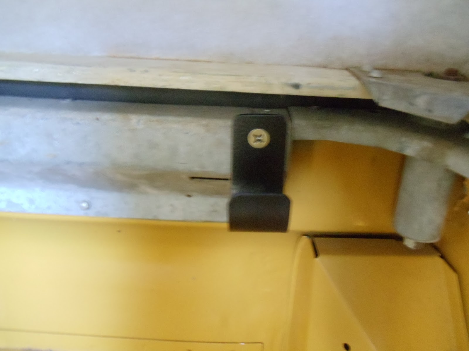
    So the local metal mfr supplied the 1 1/2"x1/8" tubing in 3 80" lengths which I could cut to fit. I also bought some 1 1/2"x1/8 flat stock 4' long. With the flat stock I set about making "J" hooks to bolt to the inner tub capping. It took me 6 trys to get 3 of equal size and shape. In the pics you can see both the J and U brackets.


    Here's my process; Taking about 8" off one of the tubes I could use it as a design aid. With it in hand I could see what would and wouldn't fit in the tub. This is how I came up with the J hook idea. To make the J hook I put the small piece of tube in my vise horizontally. At the open end I clamped the flat stock with vise grips, this I heated up with my propane torch and then using a hammer I bent it around the tube. I made the first 3 this way. They came out the right shape and size but I couldn't recess the hole for the screw head........The next step was to make the hole with recess first, THEN clamp it to the tube and heat and bend. I had to be careful to make them the same length from the hole to the bottom of the bend so the tube would sit evenly along the tub.
     Once this was figured out I set about making the center supports. Sitting in the tub I could see that each end would be slightly different but have the same basic design. A "U" welded to a flat plate. The tube would sit in the U. The front one I designed to hook over the seat bulkhead capping and bolt thru the top to keep it from sliding when weight was in the cot. I was able to make use of my first J hook attemps by using the U section for the plates. The rear is just a flat plate with a "U" welded to it. That is then bolted to the door skin. My door inner skin is steel 18ga IIRC.
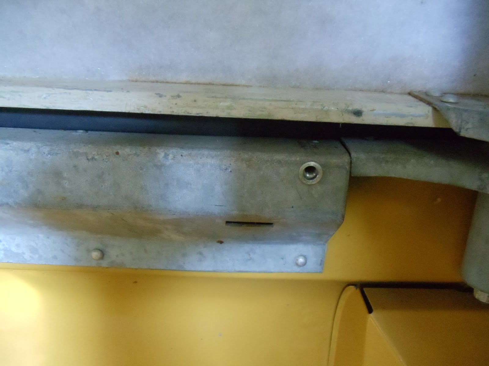
     I used 1/4-20 rivenuts to secure both the J hooks and the U plates.


I had to figure out the correct distance apart for the tubes by setting the cot up. To do this I needed to find the right length for the tubes. This was accomplished by measuring and cutting and trial fitting until the side rail fit in it's J hooks. As it was hot inside the 109 I was sweating good when I fit the cot to the tube and put it in the J hooks, then ran the other tube in and go in and closed the door. I could pull the canvas so that it was taut and get a measurement for distance. Of course it wan't going to be easy! I needed to remove the center seat back braces for the front bracket. On the rear door the bracket was right on my access hole for the rear door pull. On the good side the tube was cut to the right length!
    So the seat brackets were removed by cold chisel and drill. The U brackets carefully measured and placed. Holes were drilled and rivenuts installed. The cot with tubes installed and test fitted and tested for comfort and weight. All seemed good with the exception of the fit of the canvas, it is still too long and I have no end support figured out.
     Then all was removed and cleaned and painted. The brackets all installed after drying.


Sewing;  I figured out the length I need and tried to sew the canvas on my machine but neither I nor it was up to the task, My thread kept breaking and I broke a needle, so I'm going to take it to someone to do once I get it all figured out.

     At this point I am thinking that I can install grommets in the canvas and hook them to the seat bulkhead to keep the canvas from sliding. I may be able to do the same on the foot end too just haven't looked hard at it.

Wednesday, July 24, 2013

Land Rover air filter

     Well, It's not really Rover, but it is on my Rover. I looked around and found that K&N make a conical filter with a conical airbox. They call it Apollo. http://www.knfilters.com/universal/apollo.htm
    I was hoping that somehow I could combine the KN with the mushroom top for the raised air intake. I found an Apollo on Ebay slightly used in that it was only trial fitted and not used. Once it showed up comparing it with the shroom top it was clear that it would not be an easy fab to combine the 2 systems. So for now I have aborted that idea.  :^( I know it can be done I just do not have the resources.
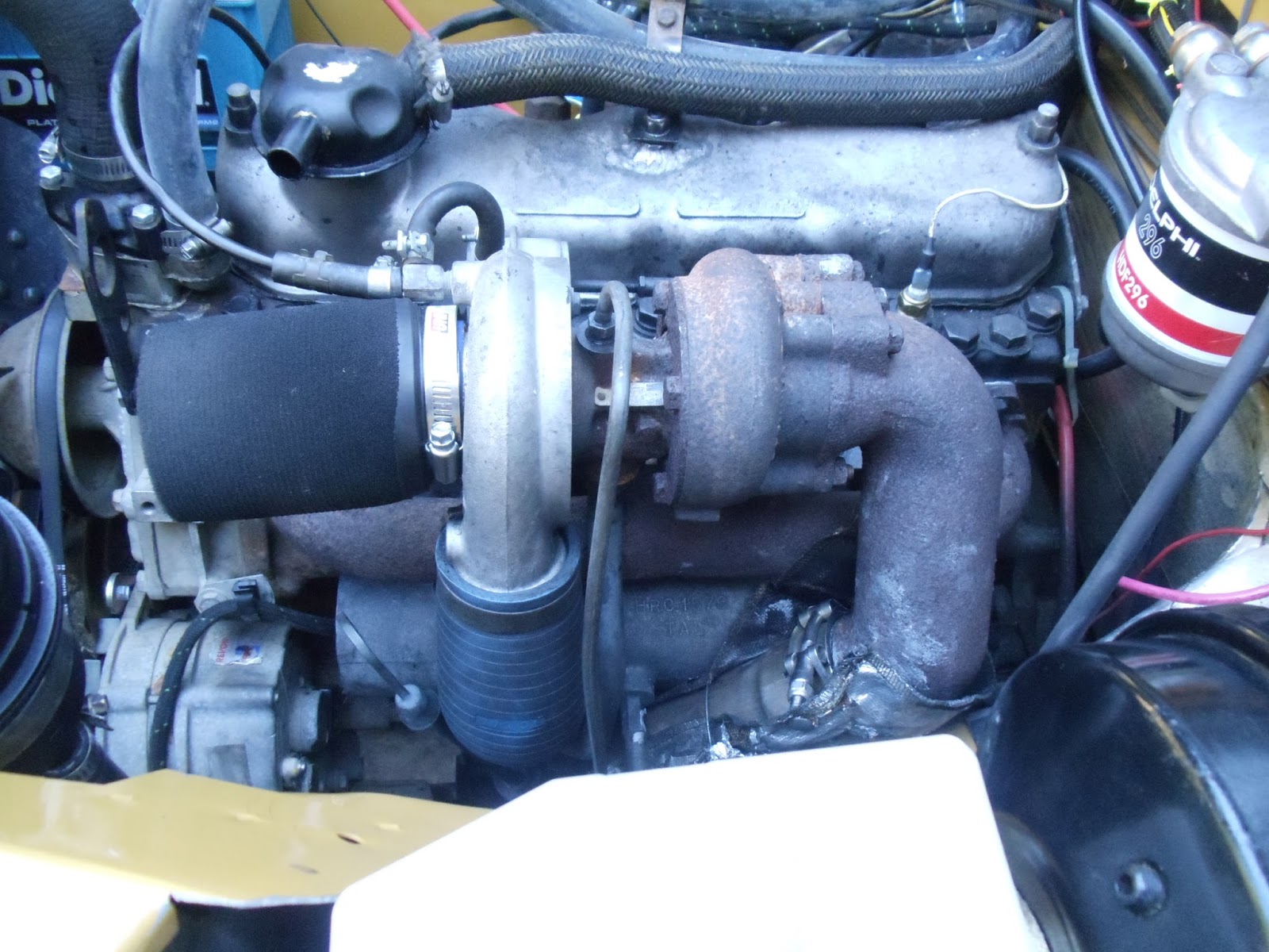
   So on to the fitting of the KN; the turbo has a 51mm intake the KN a 70mm outlet so an adapter was sourced from HPS  http://www.hps-siliconehoses.com/?gclid=CJC0qK7nyLgCFUFyQgodEiQAtg

At the same time I bought a 90 elbow in 70mm to come off the front of the adapter included in the KN kit. Once that showed up I went to work and took off the foam motorcycle filter and put on the adapter and then the Apollo.

     Then the front adapter was fitted, this necks it down from 102mm to 70mm. Since this is a push on connection it is a concern for watertightness if wading.

     You can also see that the vaccum controls coming off the turbo are not good so later I rerouted them.
     From this point on I really tried hard to figure out how I can do a raised air intake, tastefully anyway. I thought of this and that but nothing was fitting. It became a matter of moving the radiator or the air filter.


     So for now I will keep designing some way to do one in my head and stay out of deep water. I would like to move the intake out of the warm engine bay at a minimum.
     Here's where it is for now;


     You can see the vaccum hoses were switched and rerouted to clear the filter housing.

Wednesday, July 10, 2013

Land Rover exhaust..again

     So I strained my back a couple of weeks ago when I put in the floorboards. It has slowed me down somewhat. Slowly getting better and can do some things every now and then.
     I did some online searching and found out that pretty much all the 4cyl diesels from Rover use the same manifold gasket. Since I had a spare from my 2.25 diesel I went out today to put it on.
     Much to my surprise I found my brake reservior leaking.$%^&* It never ends???? It's brand new!!!! So I emailed where I bought it in the UK, we'll see what happens.

     I took off the intake and exhaust manifolds but kept the turbo in place. The nuts and threads look really rusty on it, so I didn't want to bust anything. It looks like someone's been there before as the rear bottom stud was replaced by a piece of cut off allthread. I didn't have a stud for it either so I put a bolt in.
Here is a pic of the old gasket, interestingly where the soot is you can see right thru the gasket in little holes.


You can see in the photos that #1 and #4 were both leaking putting soot all over the intake manifold.  I cleaned up the intake manifold, removing all the soot and corrosion. I wire brushed the head clean and prepped it for the new gasket.
   
     So since I have the same fiber gasket I thought I'd try something different to make it last. I checked my antisieze and it is rated to 1600F. So I put a light smear on both sides before installation. I also put antisieze on the stud ends.

     Then the intake manifold was put on. It has to go on first because there are 2 hidden bolts holding it to the head.

     Then my attention was turned to the exhaust manifold. Close inspection revealed that there was rust/exhaust gas pitting on the mating surface of the manifold tubes. These I cleaned up with my palm sander and 80 grit sandpaper. Then it could go back on.

    By now the 1 hour job had gotten on to 2 and a half hours. I kept having to take stuff off and make things loose to get the manifods off. Hoses, oil pipes, exhaust down pipe. The exhaust down pipe had to be disconnected from the engine clamp, loosened at the first joint then pushed down out of the way. Plus it was getting hot!
    I removed my sweatshirt, my teeshirt was drenched with sweat already and soon the sun would hit where I was toiling..........
    As fast as I could I started to put on the exhaust manifold, it was almost impossible to get the oil return line hooked back up. I finally had to remove it from the bottom pipe and put it on the top pipe so it would go on. The nuts behind the turbo have to be fitted next because you can't get to them when all is flush againt the head. But it is always the last nut/bolt that gives ya the most problem.
    There is a center nut between the 2 manifolds that you can't see or feel. I tried several ways to get &*$# nut and washer on. Finally I got the washer on with a small pickup magnet. I thought I then had the nut on with a deep socket and an extension. When I went to put the rachet on I heard the nut fall off. I looked for 10 minutes couldn't find it.............and of course didn't have another, oh, they are M8x1.25 by the way.
     Now the sun is on me, I'm frelling filthy and sweating profusely my back is starting to tighten up and hurt again. So I just put all the tools away and close up shop. Went inside and cleaned myself up and had some lunch. Rested my back for a bit, changed clothes and went into town for some nuts.
    By the time I returned it was still too hot and my back needed resting so I just relaxed inside. (did laundry actually)
    Around 7pm I went back out and finished the job, the nut went right on??? I thrashed around in the dirt again working the down pipe back on and tightening bits up meanwhile the brake fluid continued to drip in my face. I don't have a photo of the finished job, I'll try to remember tomorrow. But I did run it and it was much quieter.
     So here is the photo from this morning of the completed job. You'll notice I still need to figure out the air filter.

    And some good news! I recieved an email this morning LRSeries is going to replace the defective brake master cylinder. Bully for them to stand behind what they sell!

Saturday, July 6, 2013

Land Rover 109 runs...sort of

OK, so I put on the door cards after the lock barrels came in. I now have all 3 doors keyed alike.
     I used wood clamps to hold the card to the door while I drilled holes and put in screws.
     The spare tyre was set in place on the inside tray. It is not the same width as the road tyres but the same height so it can get me out to where I might be able to fix the flat.


     I actually have driven it about 100 miles now. There were some things I had wrong. You heard about the brake calipers already, and the charge lite. Now after driving it and being confirmed by a friend, the power steering wasn't working.
     So back online looking for pics and routing diagrams and a email to Timm Cooper confirmed I had the hoses running incorrectly. Again a trip to the Hose Shop with the hose ends needed and got the correct ones made up. I came home and in between helping the plumber fix a pipe under my house the offense was put right.
     Haven't driven it yet as I have discovered an exhaust leak somewhere around the manifold.

     On another front I ordered mirror arms for the hinges. I wanted Part # MRC56 but could only find #MRC4583. Supposedly it fit Series 3 hinges.
When they came I knew it was too large compared to the ones on my 88. I also discovered it did not come with the bracket to mount. So those were ordered Part #347704 and 347705, right and left. When those showed up I was exasperated! Yes they would fit the hinge but not the arms....*&*&^%$%$  So email Mark at Craddocks went back and forth then pictures. Oh the style I have thru bolt the later style style Series 3 hinges. The MRC56 arms are no longer made. There is no bracket adapting the MRC4583 to the Series 2/2a hinge.
     So I searched the web.............nothing. Couldn't find any MRC56's or adapting brackets..................
    Soooo I made my own! Using 14ga sheet metal I cut out 2 pieces, 3.5x2.5". Marking a 1' line I used that for the hinge side. Then inserted in my vise and bent it with heat at a 90 degree. This 90 I set on top of a piece of 1/2" tubing and bent it again in the opposite direction creating a kinda Z shape. Then drilled for the hinge holes and the mirror arm holes---both different. Painted, dried and mounted. Mounting was a pain in the a** having to readjust the doors.
     Anywho here's the pics;


 Now I'm going to try to load a video of the first test drive. The one I found out the brakes weren't working good on.
 
Wow it worked!
 
So here is a pic of the front of the 109 with all the mirrors on.