OK, I've been wondering what kind of mileage I've been getting. I haven't been driving very far, mostly in a 20 mile radius and the main speed limit up and down the valley I live in is 35. Been on the freeway for short distances a couple of times, forgot to look at what my max speed was.
I ran almost a tankful over the last couple of weeks whilst making sure my gps was on. I think(fingers crossed) that I got all the mileage, if not I'm only a mile or 2 off.
So on Friday I filled up the tank and checked the gps against the speedo odometer. The gps showed 250.1 miles and the odo 201.6. a 50 mile difference although the speedo indicates in a wonky way, somewhat close to the actual speed.
The numbers show that I used 8.98 gallons(US) which was approximately 7/8 empty on the gauge. Covering 250.1 miles gives me 27.84 miles per gallon.
That's good and now I know that I still have 3 gallons in the tank.

Saturday, October 14, 2017

Saturday, September 23, 2017
Dash cam for the Land Rover
Hey, I got a tip from a vlogger, Seth's bike hacks, about a good dash cam, the Anker ROAV. I already have one of their power packs and really like it so it was a no brainer to get the cam on. Amazon for $90. https://www.amazon.com/Dashboard-Recorder-Wide-Angle-G-Sensor-Recording/dp/B06XNSDRW8/ref=sr_1_1?ie=UTF8&qid=1506196675&sr=8-1&keywords=roav+dash+cam
It came the other day and it took me awhile to figure out where and how I wanted to mount it. That and I still have to get a micro SD card for it.

After sitting in the drivers seat and holding it up in different places and weighing the pro's and con's such as ease of visibility and access for the card, wiring and removal and not blocking the visibility out the windscreen in critical locations.
What I came up with was a clip on over the roof inside gutter and allowing the cam to hang just below the windscreen frame enough to not block the cam's view with either the frame or the rearview mirror. I also took advantage of the existing holes for the sun visor I don't have. This will keep it from bouncing off and getting crazy from the vibrations. (I hope!)

I made a prototype out of aluminum cause it's easy to work with then I made one out of some scrap stainless I had laying about.


Here it is hangin up in place. I found #6 sheet metal screws fit right in.

Then it was a matter of mounting the cam,

Running the power;


Pluggin it in; making the wire so it won't vibrate too much;

I tied the excess wire and stashed it in the gutter;
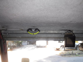
Lastly, power it up!

So it is not permanently mounted and if it is too cumbersome I can move/remove it.
It came the other day and it took me awhile to figure out where and how I wanted to mount it. That and I still have to get a micro SD card for it.

After sitting in the drivers seat and holding it up in different places and weighing the pro's and con's such as ease of visibility and access for the card, wiring and removal and not blocking the visibility out the windscreen in critical locations.
What I came up with was a clip on over the roof inside gutter and allowing the cam to hang just below the windscreen frame enough to not block the cam's view with either the frame or the rearview mirror. I also took advantage of the existing holes for the sun visor I don't have. This will keep it from bouncing off and getting crazy from the vibrations. (I hope!)

I made a prototype out of aluminum cause it's easy to work with then I made one out of some scrap stainless I had laying about.


Here it is hangin up in place. I found #6 sheet metal screws fit right in.

Then it was a matter of mounting the cam,

Running the power;


Pluggin it in; making the wire so it won't vibrate too much;

I tied the excess wire and stashed it in the gutter;
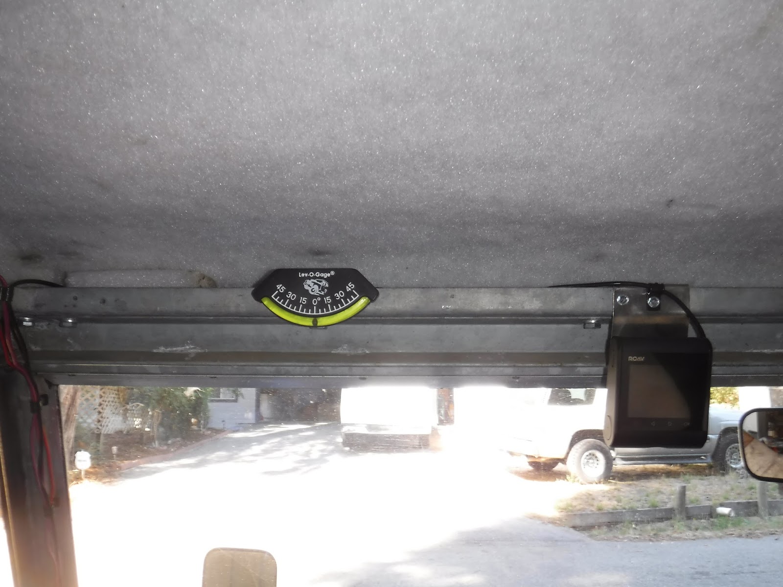
Lastly, power it up!

So it is not permanently mounted and if it is too cumbersome I can move/remove it.
Tuesday, August 29, 2017
Roof rack gets updated
My first post on making a roof rack is here;
http://poppageno.blogspot.com/2014/04/land-rover-109-roof-rack.html
Then I followed it up with a rack designed around my Off Road lites;
http://poppageno.blogspot.com/2014/10/off-road-lites.html
Granted there is not much info on the front part of the rack. Basically I just cut and welded some Super strut into a square that held my Hella 2000's.

After I figured out how to sleep inside I sold my roof top tent. Now my roof rack didn't quite fit what I wanted it to do. Hold things, maybe even some sort of sunshield.
Well I went to Home Depot and bought 3 more pieces of Super-Strut. Figuring on making 2 longitudinal sides and 1 center one. I got eager and coated them with truck bed liner first. Wrong!
First I should have figured out where to put them. As they were drying I did this. I looked down the sides and figured I could just use the existing inboard bolts on the towers. Simples!


It was friggin hot outside to work but I started unbolting the right side inboard bolts, I got halfway done and had second thoughts about this being the best way. My main reasoning was that I wanted the rack to be flexible, that is I could reshape it if I needed to. Unbolting and moving the bars where ever they worked the best. This meant leaving the towers alone. So I put all the tower bolts back and moved the bar over to the first available slot. That is when I realized that I had not cut them to length........

I had already decided that I wanted a 1 hole overhang on the front and I would bring the back end almost even with the rear of the roof. This will be if I need/want to attach any tarps or for rigging. The 2 outboard ones were cut and then re-coated with bed liner. and now ready to install.
Starting with the ends for support I loosely bolted the outboard ones up.

And that is when the real work began......the bolt holes on the welded up section did not line up with the new pieces :^0 There went 2 hours...

The next morning I began the great labor of the day. I used a jigsaw to cut out the side pieces on the welded section. Next I removed the back 2 crossbars and ground off the old weld and re-bedlinered(NEW WORD!) the bare metal. Trust me it wasn't easy, climbing up and down on the roof, cutting and grinding up there and then realizing it would be tons easier if I took it off the roof. Unbolting the gutter clamps. figuring out how to clamp the darn thing so I could grind on it. Re-spraying. then putting them back on the roof.


http://poppageno.blogspot.com/2014/04/land-rover-109-roof-rack.html
Then I followed it up with a rack designed around my Off Road lites;
http://poppageno.blogspot.com/2014/10/off-road-lites.html
Granted there is not much info on the front part of the rack. Basically I just cut and welded some Super strut into a square that held my Hella 2000's.

After I figured out how to sleep inside I sold my roof top tent. Now my roof rack didn't quite fit what I wanted it to do. Hold things, maybe even some sort of sunshield.
Well I went to Home Depot and bought 3 more pieces of Super-Strut. Figuring on making 2 longitudinal sides and 1 center one. I got eager and coated them with truck bed liner first. Wrong!
First I should have figured out where to put them. As they were drying I did this. I looked down the sides and figured I could just use the existing inboard bolts on the towers. Simples!


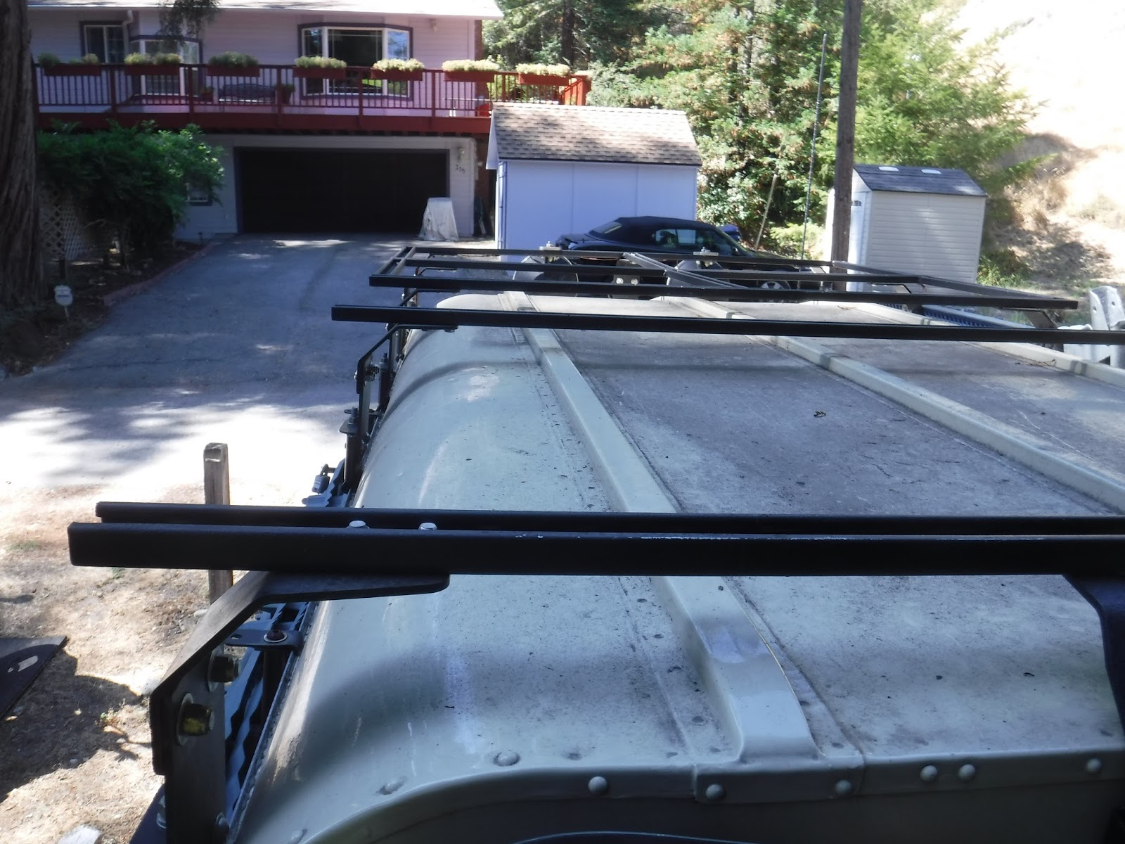

It was friggin hot outside to work but I started unbolting the right side inboard bolts, I got halfway done and had second thoughts about this being the best way. My main reasoning was that I wanted the rack to be flexible, that is I could reshape it if I needed to. Unbolting and moving the bars where ever they worked the best. This meant leaving the towers alone. So I put all the tower bolts back and moved the bar over to the first available slot. That is when I realized that I had not cut them to length........

I had already decided that I wanted a 1 hole overhang on the front and I would bring the back end almost even with the rear of the roof. This will be if I need/want to attach any tarps or for rigging. The 2 outboard ones were cut and then re-coated with bed liner. and now ready to install.
Starting with the ends for support I loosely bolted the outboard ones up.

And that is when the real work began......the bolt holes on the welded up section did not line up with the new pieces :^0 There went 2 hours...

The next morning I began the great labor of the day. I used a jigsaw to cut out the side pieces on the welded section. Next I removed the back 2 crossbars and ground off the old weld and re-bedlinered(NEW WORD!) the bare metal. Trust me it wasn't easy, climbing up and down on the roof, cutting and grinding up there and then realizing it would be tons easier if I took it off the roof. Unbolting the gutter clamps. figuring out how to clamp the darn thing so I could grind on it. Re-spraying. then putting them back on the roof.
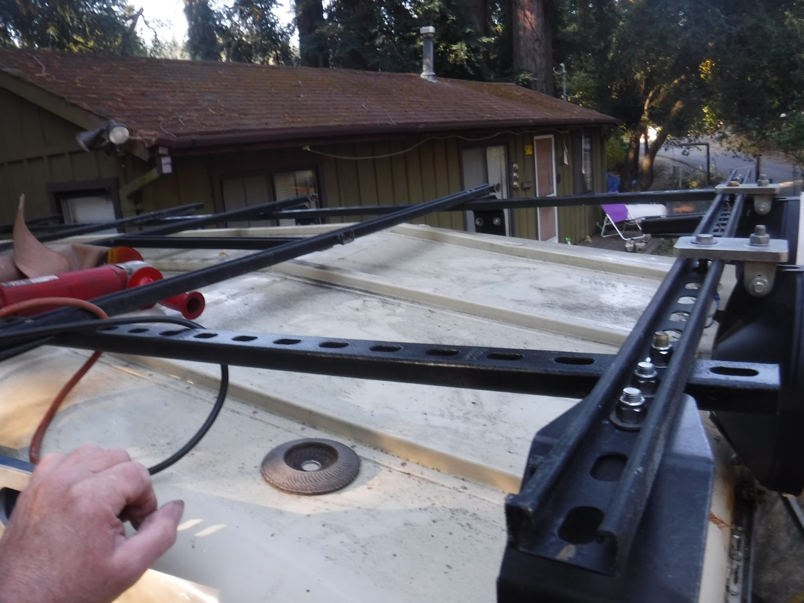

Since the longitudinal side bars were there I had to figure out where to put the other cross bars. I tried measuring and setting it up evenly but the gutter mounts for the sand ladders are in the way so I got it as even as I could. There is another issue with the center long bar. The front tower is centered on the roof and the cross bar does NOT have a center hole.

This means the center long bar is crooked. In order for it to line up with the closest holes.

But it was coming together! The final thing was re-mounting the Hi-lift jack. I knew from taking measurements that it would not go back on the same holes.

Sure enough after making the swap, I offered up the jack and Viola!

Put away tools and take the money shots after 4 hours of sweaty work and a trip to the hardware store for nuts and bolts 3/8"-24x3/4".


Sunday, August 27, 2017
200TDI injector pump replaced
I hope that you have read this post first; http://poppageno.blogspot.com/2017/03/fuel-injection-pump-200tdi.html
From it you will know that I took parts from 1 pump to make another run. Well it worked somewhat. The engine ran but until really warm was sluggish off the line and wouldn't climb a hill worth a shit! I had to be in 1st or high revving 2nd to get up my hill, one which I used to climb easily in 2nd and accelerate at the top. Now I almost wouldn't make it up in 2nd. On another local 45mph hill I was resorting to 3rd gear to do around 35 to get over.
I knew it had to be the pump as nothing else had changed. So I studied my options. One was a new pump at around $1200. Another was send it to the local repair place 80 miles away, for $1000+ parts. Or buy a second hand used one, that seemed to be around $500 to $900 on Fleabay. None of these were cheap and within my meager budget.
So I suffered thru it until recently when I sold my 88. Then cash in had I made an executive decision.............
I bought a new one.
I found out that the injector pump comes under 2 part numbers depending on if it is Leyland or Rover. The Leyland number is ETC8625 and the Rover number is ERR0459 or sometimes ERR459. Either way they both carry the Bosch number 0460414069.
My choice was to go through Bearmach and get a ETC8625 for @$1215 w/$30 shipping. My thinking was that this would probably be around the same price as getting one of mine rebuilt. Especially knowing that I would need a shim and cam plate on one of them and who knows on the other.
Ordered on a Thursday and arrived on the next Monday!

It came with new stop solenoid and crush washers and fuel inlet banjo bolt.

So after taking care of business during the week I picked yesterday to swap out the pumps. I figured a couple of hours. It was going to be 100F later in the day so I started early at 0900.

I kinda knew what tools I needed and dragged them out and set the #1 at TDC and pulled the cover off the timing pulley and stuck in the locking pin.

Then it was a matter of pulling off the hoses and pipes to get at the injector pump. Once all that was out of the way I (following the book closely) Locked the pump with the side lock and pulled the 3 bolts on the pulley and removed the timing pin. Took out the top bolt on the oil filter adapter for clearance issues and unbolted the rear pump bracket and finally the 3 nuts holding the pump to the cover. Easy peasy, I just wish I had smaller hands as it is pretty tight in some places!
Before the pump is removed the timing pulley needs to be locked in place. There is a round disc tool that accomplishes this. Unlike the last time I had a heck of a time getting the bolts in to lock it up. I wound up removing a cadmium plated locking plate and this solved the issue, but I spent 15-20 minutes trying to get the frelling bolts in.
Taking it out I compared the old with the new and swapped parts such as fuel inlet fitting and locking pin. Here I noticed that there is a rubber thingy(technical term) on the diaphram of the new pump that is missing on mine.

It was ready so I brought it over for the install.

One of the things I had to swap over was the locking pin. This is necessary to align the pump and the timing plate and hence the crank et al. With the pump properly aligned it slide smoothly in place. It was then a matter of reversing all the installation work.

I only forgot to tighten the nuts on the injector pipes for #3&4. Other than that NO LEAKS!!
Here is one with it running.

Next up was the test drive. I should say that I didn't bleed any lines after the install as the Bosch VE pumps are self bleeding. It did take, what, 10-20 seconds on the starter to fill the pump and get ignition.
So I cleaned up a bit and threw the tools int the back and went down the hill to the mailboxes and back. I noticed right away just pulling out of the drive it no longer was sluggish and responded properly to the touch of the throttle. I went down the hill with no problem other than the damn smoking issue is still there(sigh) and turned around. coming back up the hill would be the test. I set out in first and shifted to second and kept the rpms low, about 3/4 of the way up I gave it some wellie and it spun up and charged up the rest of the way. SUCCESS!
After the test drive I opened up both my now spare pumps and swapped the parts back. Maybe my original spare works, who knows? All told it took me 3 hours and it was 93F when I was finished. So I went inside and showered and napped and later in the afternoon I drove into town and picked up a 6-pack for a job well done reward :^)
Now to tackle the smoke and oil consumption issues, most likely a ring job. :^(
Updated; Aug 28 2017, I got to say my 109 runs great now. I went up a hill that with the original pump I could do in 4th, then it was 35 in 3rd after I swapped parts into it, yesterday I went up in 4th OD with pedal to spare! WOOT! WOOT!!
Still smokes though..... :^(
From it you will know that I took parts from 1 pump to make another run. Well it worked somewhat. The engine ran but until really warm was sluggish off the line and wouldn't climb a hill worth a shit! I had to be in 1st or high revving 2nd to get up my hill, one which I used to climb easily in 2nd and accelerate at the top. Now I almost wouldn't make it up in 2nd. On another local 45mph hill I was resorting to 3rd gear to do around 35 to get over.
I knew it had to be the pump as nothing else had changed. So I studied my options. One was a new pump at around $1200. Another was send it to the local repair place 80 miles away, for $1000+ parts. Or buy a second hand used one, that seemed to be around $500 to $900 on Fleabay. None of these were cheap and within my meager budget.
So I suffered thru it until recently when I sold my 88. Then cash in had I made an executive decision.............
I bought a new one.
I found out that the injector pump comes under 2 part numbers depending on if it is Leyland or Rover. The Leyland number is ETC8625 and the Rover number is ERR0459 or sometimes ERR459. Either way they both carry the Bosch number 0460414069.
My choice was to go through Bearmach and get a ETC8625 for @$1215 w/$30 shipping. My thinking was that this would probably be around the same price as getting one of mine rebuilt. Especially knowing that I would need a shim and cam plate on one of them and who knows on the other.
Ordered on a Thursday and arrived on the next Monday!

It came with new stop solenoid and crush washers and fuel inlet banjo bolt.

So after taking care of business during the week I picked yesterday to swap out the pumps. I figured a couple of hours. It was going to be 100F later in the day so I started early at 0900.

I kinda knew what tools I needed and dragged them out and set the #1 at TDC and pulled the cover off the timing pulley and stuck in the locking pin.

Then it was a matter of pulling off the hoses and pipes to get at the injector pump. Once all that was out of the way I (following the book closely) Locked the pump with the side lock and pulled the 3 bolts on the pulley and removed the timing pin. Took out the top bolt on the oil filter adapter for clearance issues and unbolted the rear pump bracket and finally the 3 nuts holding the pump to the cover. Easy peasy, I just wish I had smaller hands as it is pretty tight in some places!
Before the pump is removed the timing pulley needs to be locked in place. There is a round disc tool that accomplishes this. Unlike the last time I had a heck of a time getting the bolts in to lock it up. I wound up removing a cadmium plated locking plate and this solved the issue, but I spent 15-20 minutes trying to get the frelling bolts in.
Taking it out I compared the old with the new and swapped parts such as fuel inlet fitting and locking pin. Here I noticed that there is a rubber thingy(technical term) on the diaphram of the new pump that is missing on mine.

It was ready so I brought it over for the install.

One of the things I had to swap over was the locking pin. This is necessary to align the pump and the timing plate and hence the crank et al. With the pump properly aligned it slide smoothly in place. It was then a matter of reversing all the installation work.

I only forgot to tighten the nuts on the injector pipes for #3&4. Other than that NO LEAKS!!
Here is one with it running.

Next up was the test drive. I should say that I didn't bleed any lines after the install as the Bosch VE pumps are self bleeding. It did take, what, 10-20 seconds on the starter to fill the pump and get ignition.
So I cleaned up a bit and threw the tools int the back and went down the hill to the mailboxes and back. I noticed right away just pulling out of the drive it no longer was sluggish and responded properly to the touch of the throttle. I went down the hill with no problem other than the damn smoking issue is still there(sigh) and turned around. coming back up the hill would be the test. I set out in first and shifted to second and kept the rpms low, about 3/4 of the way up I gave it some wellie and it spun up and charged up the rest of the way. SUCCESS!
After the test drive I opened up both my now spare pumps and swapped the parts back. Maybe my original spare works, who knows? All told it took me 3 hours and it was 93F when I was finished. So I went inside and showered and napped and later in the afternoon I drove into town and picked up a 6-pack for a job well done reward :^)
Now to tackle the smoke and oil consumption issues, most likely a ring job. :^(
Updated; Aug 28 2017, I got to say my 109 runs great now. I went up a hill that with the original pump I could do in 4th, then it was 35 in 3rd after I swapped parts into it, yesterday I went up in 4th OD with pedal to spare! WOOT! WOOT!!
Still smokes though..... :^(
Saturday, May 27, 2017
Timing a 200TDI in a 109 Land Rover
Hullo,
If you are a regular follower you might remember that I had an issue with my fuel injection pump. Ever since I resolved the broken shim and swapped the damaged bits my 109 hasn't been the same.
It was smoking(nothing new there) and under powered(that's new). When pulling off from a cold start it felt like it was in third gear. Once the engine warmed up it worked better, but I still had underpower issues on hills of any type. I had to have high revs in first or second to get up the street to my house, which I found out the hard way......
I finally figured out that I needed to re-time the injector pump. Either the parts I swapped were not working right or the timing wasn't correct. Checking the timing would be the least costly thing to do.
According to the manual to time the 200 you have to put a pin in the drain plug hole for the flywheel when the #1 cylinder is a TDC. The timing mark on the crankshaft pulley now lines up with one of the strengthening webs on the timing cover. Then you pin the injector pump with another pin to keep it from moving. At this point if the injector pin won't go in you have to loosen the pulley on the injector pump and turn it until the pin fits. Tighten it all up and yer done! (IIRC)
My first big problem is that the drain plug hole for the flywheel housing is blocked by the crossmember. No access, zip, zero, can't even see it without a mirror. I fretted and planned for over a month on how I was going to cut my crossmember and bolt up some steel to retain the chassis integrity. I asked on other forums how they did it. Most just lined up the crankshaft timing mark with the web and called it good.
Which leads to my second problem; I can not get a good visual on the timing mark and the web to see how well it is lined up. The radiator and electric fan are in the way, even using a mirror.......Grrrrrr!
I made a pointer with a magnet and put it on the timing mark, but the web is so wide I couldn't be sure how close I was. I mean it ran but was underpowered.
I made a pointer to clamp to the web with a fine point but I can't even get my hand in there to clamp it on........Arrrrgh!......
Not wanting to cut the crossmember I kept thinking.......tick.......tick........tick................clunk.
Knowing I needed to find TDC I decided to pull the #1 fuel injector and stick a bicycle spoke down it and watch to see TDC. Once I put it in I knew it wouldn't be close enough. I needed my dial indicator but I don't have a long enough rod to touch the piston....grrr.....
Then it hit me::THWAK!:: IF my dial calipers would fit down the injector hole I could use the depth finder feature to watch the piston move and find TDC!
It fit!

It took a bunch of tries to figure out exactly how to do it. and getting consistent readings. I found that while I held the fixed and moveable parts of the caliper in the hole I could feel when the piston hit TDC before I visually realized that the gauge had stopped moving.

So I now had TDC dialed in, pun intended ;^)

My next step was to test fit the injector timing pin. And as I thought, it would not fit, the timing was indeed off. According to the book my fix was to move the engine off TDC until the timing pin slipped in, then on the side of the injector pump remove the keeper plate and tighten the bolt and lock the pump. Ya then slacken the 3 bolts on the injector pump gear, turn the engine to TDC. Check the injector pump timing pin fitment(should be easy) and tighten the 3 retaining bolts to the correct torque.
Back on the side of the injector pump loosen the locking bolt and replace the keeper plate and re-tighten. Remove the timing pin.
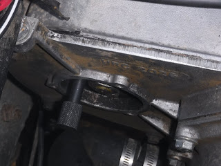
I re-installed the injector and lines and fired it up. Just a quick trial in my drive shows it pulls away stronger from a stop. I haven't been able to drive it anywhere yet.
How you ask, did I ever turn the crank and hold on to the calipers and watch them all at the same time? If you remember I use my handcrank that I modified to take a socket which fits the bolt on the crankshaft pulley. Which I turned with my foot.

If you are a regular follower you might remember that I had an issue with my fuel injection pump. Ever since I resolved the broken shim and swapped the damaged bits my 109 hasn't been the same.
It was smoking(nothing new there) and under powered(that's new). When pulling off from a cold start it felt like it was in third gear. Once the engine warmed up it worked better, but I still had underpower issues on hills of any type. I had to have high revs in first or second to get up the street to my house, which I found out the hard way......
I finally figured out that I needed to re-time the injector pump. Either the parts I swapped were not working right or the timing wasn't correct. Checking the timing would be the least costly thing to do.
According to the manual to time the 200 you have to put a pin in the drain plug hole for the flywheel when the #1 cylinder is a TDC. The timing mark on the crankshaft pulley now lines up with one of the strengthening webs on the timing cover. Then you pin the injector pump with another pin to keep it from moving. At this point if the injector pin won't go in you have to loosen the pulley on the injector pump and turn it until the pin fits. Tighten it all up and yer done! (IIRC)
My first big problem is that the drain plug hole for the flywheel housing is blocked by the crossmember. No access, zip, zero, can't even see it without a mirror. I fretted and planned for over a month on how I was going to cut my crossmember and bolt up some steel to retain the chassis integrity. I asked on other forums how they did it. Most just lined up the crankshaft timing mark with the web and called it good.
Which leads to my second problem; I can not get a good visual on the timing mark and the web to see how well it is lined up. The radiator and electric fan are in the way, even using a mirror.......Grrrrrr!
I made a pointer with a magnet and put it on the timing mark, but the web is so wide I couldn't be sure how close I was. I mean it ran but was underpowered.
I made a pointer to clamp to the web with a fine point but I can't even get my hand in there to clamp it on........Arrrrgh!......
Not wanting to cut the crossmember I kept thinking.......tick.......tick........tick................clunk.
Knowing I needed to find TDC I decided to pull the #1 fuel injector and stick a bicycle spoke down it and watch to see TDC. Once I put it in I knew it wouldn't be close enough. I needed my dial indicator but I don't have a long enough rod to touch the piston....grrr.....
Then it hit me::THWAK!:: IF my dial calipers would fit down the injector hole I could use the depth finder feature to watch the piston move and find TDC!
It fit!

It took a bunch of tries to figure out exactly how to do it. and getting consistent readings. I found that while I held the fixed and moveable parts of the caliper in the hole I could feel when the piston hit TDC before I visually realized that the gauge had stopped moving.

So I now had TDC dialed in, pun intended ;^)

My next step was to test fit the injector timing pin. And as I thought, it would not fit, the timing was indeed off. According to the book my fix was to move the engine off TDC until the timing pin slipped in, then on the side of the injector pump remove the keeper plate and tighten the bolt and lock the pump. Ya then slacken the 3 bolts on the injector pump gear, turn the engine to TDC. Check the injector pump timing pin fitment(should be easy) and tighten the 3 retaining bolts to the correct torque.
Back on the side of the injector pump loosen the locking bolt and replace the keeper plate and re-tighten. Remove the timing pin.

I re-installed the injector and lines and fired it up. Just a quick trial in my drive shows it pulls away stronger from a stop. I haven't been able to drive it anywhere yet.
How you ask, did I ever turn the crank and hold on to the calipers and watch them all at the same time? If you remember I use my handcrank that I modified to take a socket which fits the bolt on the crankshaft pulley. Which I turned with my foot.

Saturday, May 6, 2017
Land Rover prop shaft seal repair
OK, OK,... I spent most(all) of my afternoon replacing the seal in the sliding section of my rear propshaft. Why that long I hear you ask, I'll tell you why..
Mine did not have anything but grease under the nut. I have a spare front for an 88 so I took that apart to see what was in there since I can't find anything online that will tell me.
Here's what I found, first that directly under the nut is a split steel washer;

Under that is a split fiber washer;

Alas and alack, I had neither of those on hand and no place to get them. So I improvised I got some cork gasket material some of which is rubberized and figured that I could use 2 sizes to get close to the 5/32" thickness of the original. I measured the OD of the propshaft sliding section for the ID of my seal and the ID of the nut for the OD of my seal. Then using a compass I drew them and cut them out with a safety blade. I made 4, 2 sets so I could have a spare in case I screwed up.


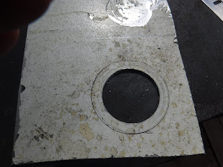


Mine did not have anything but grease under the nut. I have a spare front for an 88 so I took that apart to see what was in there since I can't find anything online that will tell me.
Here's what I found, first that directly under the nut is a split steel washer;

Under that is a split fiber washer;
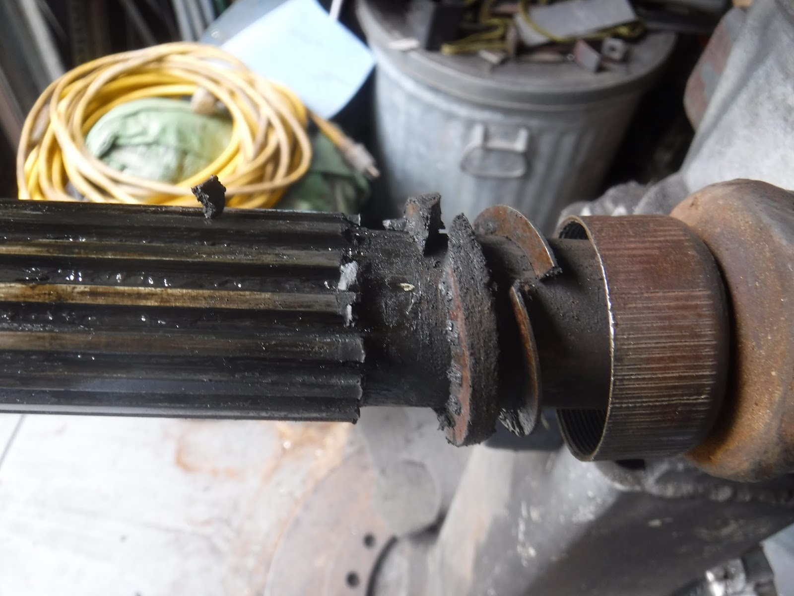
Alas and alack, I had neither of those on hand and no place to get them. So I improvised I got some cork gasket material some of which is rubberized and figured that I could use 2 sizes to get close to the 5/32" thickness of the original. I measured the OD of the propshaft sliding section for the ID of my seal and the ID of the nut for the OD of my seal. Then using a compass I drew them and cut them out with a safety blade. I made 4, 2 sets so I could have a spare in case I screwed up.


And I wound up with,(one set is stacked up);

I test fit the seals on the shaft;

Good to go!
Then came the hard part! I had to make a split washer. I looked thru my scrap and could not find a suitable piece of steel so I made one from Birmabright. I don't know if it will work but I guess I'll find out. I will also keep my eyes out for some steel to make another one from.
Using my 1-3/16" hole saw I cut out the ID. It is too large as the shaft is 1-5/32" but it was what I have. Then I laid out the steel ring and marked the OD.

Tin snips made a rough cut out and I used my angle grinder in a vise with a flap wheel on it to remove the excess material.


It took FOREVER to get my ring to fit inside the nut, working with a file but I got it. As I was doing this I checked to make sure I was keeping the ID centered when it hit me..........I could use the old ring as a template and file to it's edge.
Pulling some vise grips from the tool box I clamped the 2 bits together and filed away. Second revelation I could do this with the seals too! My first seals got tossed out as the ID and OD's were too large. Now 2 vise grips were employed to hold the materials together while I used the Dremel to quickly make the seals.


At first I cut a triangle to allow the Dremel tool access to the ID, but then I discovered I could just grind right thru the cork. Takes about 3 min to make a seal now.
I split the seals on a 45 sideways and the metal washer on a 90. Put some anti-seize on the threads, lined up the balance marks and tightened the nut. I greased it the other day so unless I find out different it is good to go!

My slip joint travels 2". I learned a lot today, I hope you did too!
Subscribe to:
Posts (Atom)