Well when we last left our intrepid rebuild the seat base and RH seat were put in. Since then the winter weather has set in and the daylight hours shorter. This and a Christmas trip to Death Valley slowed my progress down not to mention the issues I had with stuff.
So let's get on with the show!---
It took a lot of fiddling around to get the steering column all to work. I decided that I wanted to retain my spoked steering wheel. The Series 2 column used a fiber bushing inside the top of the outer column. The Series 3 uses a bearing in the top. Of course the ID(inner diameter) is different between the 2 columns, with the Series 2 being larger. That's a good thing! The other bit of seat of the pants engineering is the fact that the Series 3 steering wheel splines fit the splines on the U-joint for the lower steering section. That meant that I needed to have the top of the Series 2 inner column welded to the top of the Series 3 inner column and have the Series 2 machined down to fit the Series 3 bearing. Is that clear as mud? Well, it took care of the inner column.


The outer column didn't need any length changes but now I needed a lower inner column support. For this was chosen to put a Series 3 top bearing(#RTC324) to support the Series 3 splined shaft now residing at the bottom. It took a bit to find one online and they are expensive! The thing I found out though was the OD(outside diameter) of the bearing was smaller than the ID of the outer column. Crap can't anything be easy? My solution was to use a piece of stainless steel strapping and cut it lengthwise so the bearing was a tight fit.


Next up was to figure out how to secure the bottom of the outer column so the whole thing wouldn't move around. I started out trying to make a simple L shaped bracket to bolt to the bulkhead support and the flange on the bottom of the column. In the process of doing this I realized that I wanted to shield the lower bearing from debris with a rubber seal. I went ahead and drilled out an old piece of axle bump stop mount from my Rangie that the bumper had fallen off of. I replaced the bump stop after the Christmas trip. I layed out for the center hole for the inner column and the 4 holes for the flange. Then with drills and Dremmel tool made the thing fit! The rubber seal was made with a piece of truck mudflap, the center hole for the shaft was a tight fit to prevent contamination. I greased up the lower bearing with Phil Wood waterproof grease and installed the whole thing.........finally!

Then there was the exhaust system...... I had asked one of the local exhaust shops to come up and look at what I needed and give me an estimate for a stainless system. Well, they came up and looked around and never got back to me with an estimate. WTF? So I looked around on the web and found a place in the UK that does this conversion already. So I didn't get one in stainless figuring that I (hopefully) will get to go overseas and getting a mild steel one fixed in a third world country will be eaiser. So after a series of emails I ordered a kit from Steve Parker Land Rovers LTD (www.steve-parker.co.uk)
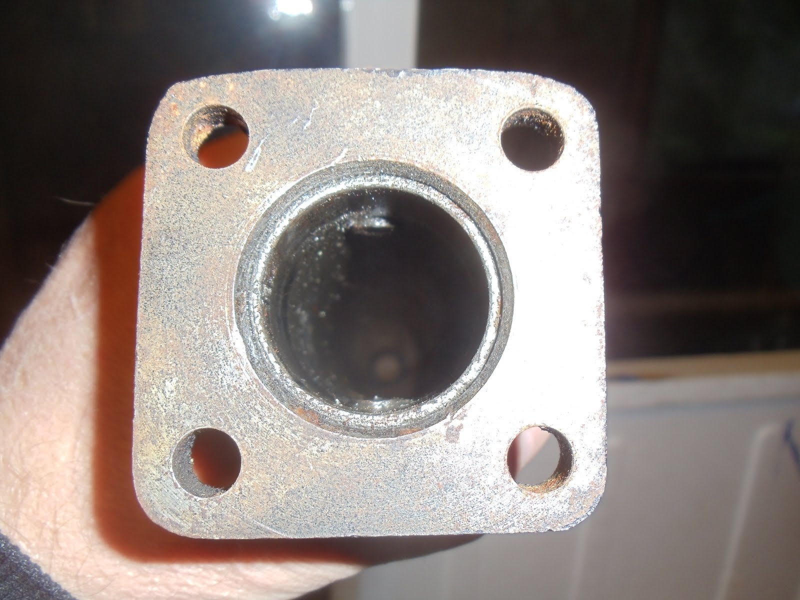
What I ordered was the 19J motor conversion for the LWB kit. I guess this is for the Series 3 109's. If you remember mine is a Series 2 109. So as typical it didn't just bolt up. The first thing was the bolt hole for the downtube bracket from the turbo was in the wrong place, I had to fit and mark and redrill a hole.


After that was figured out I started to put the system together. Well the second and third pipe didn't fit right. I wanted to know if it was just me and to see my options. So I asked Linus to come up and help me put it together. With his help we were able to put together the whole system and see where I would need to make new hanger brackets. Linus did agree with me that the second and third pipe connection was wrong also the third pipe was too short.
During all this the radiator was put in and filled with premixed 50/50 coolant.
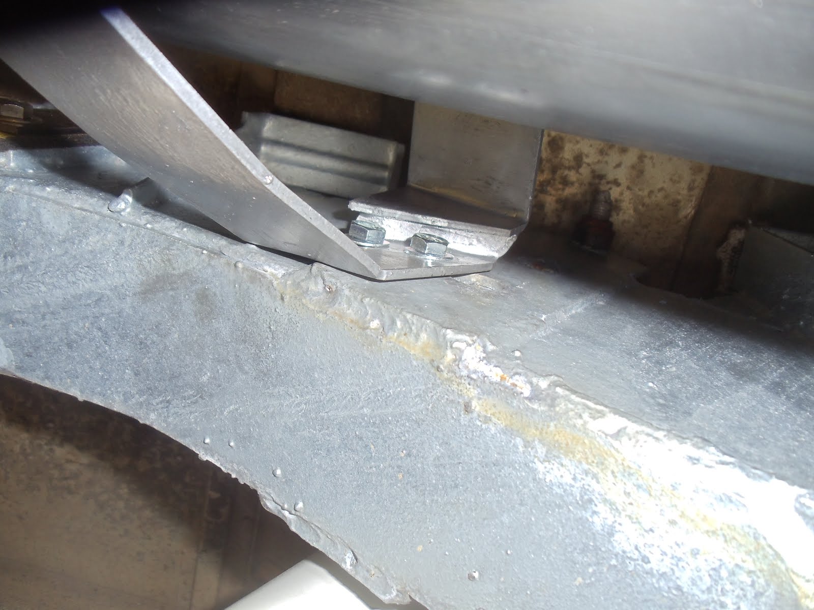
I emailed Steve Parker to make sure I had the right system and had installed it correctly. After them sending me pictures of the installation and confirming that I did have the right kit. I asked my son-in-law Andy to come over and take a look. Andy is also a 4wheeler and has a modified rock crawler Jeep which he built the roll cage for. As well as this he is a plumber by trade (Absolute Plumbing) so he knows tube bending. We crawled under the 109 and took a look, he agreed that it wasn't right and made some suggestions. He produced the angle guage you see in the pictures and we figured that the second pipe needed a 10deg additional bend and the third tube around 3" more length.


So the pics of the angle finder and the interferance of the third pipe and crossmember were emailed to Steve Parker, again to check with the fittment. To his credit after a week of waiting Steve himself answered the issue. When they do the installation they add 1.5" to the third pipe, so he recommended this. Nothing was said about the bend. Armed with this info I took the 2 pieces to Bobby's Pit Stop (www.bobbyspitstop.com) where they added the 1.5" to the third pipe and bent the #2 pipe 10 more degrees.

I took it home and it went on like it should have the first time!Next up was making a hanger for the third pipe since this system was not like the orginal system and needed new brackets for the third pipe, muffler and tail pipe.
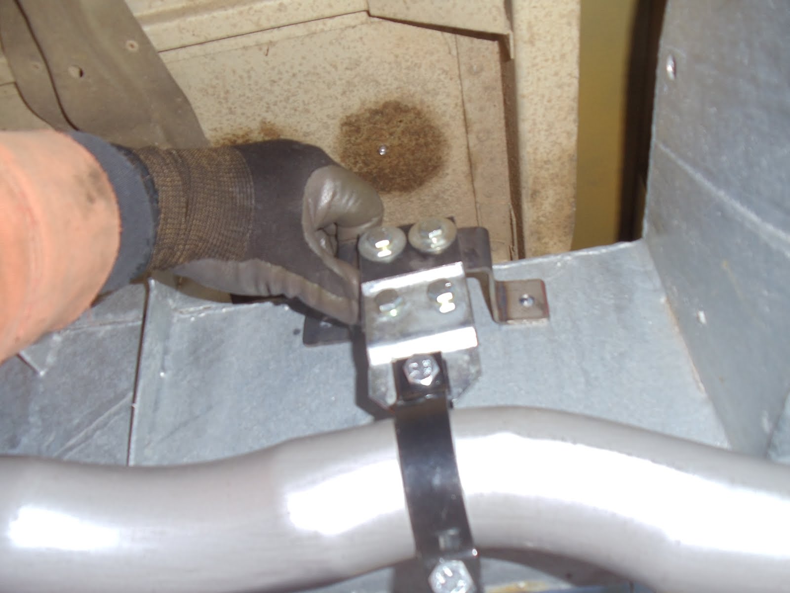
To do this the muffler was mocked up to the third pipe and held in place(my left arm!) with the hanger on the pipe I could mark where the hanger bracket needed to be. Then taking a piece of 1/8x1 flat stock I made the bracket. I opted for thru bolting the bracket by drilling holes thru the frame and using 4' 5/16 bolts UNF.
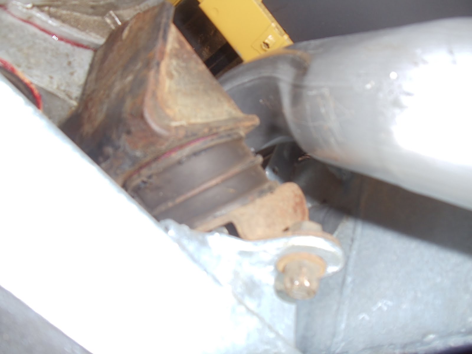
After the third pipe was hung I could move on to the muffler. This system hangs the silencer next to the frame in front of the axle. Again mocking up the muffler and marking holes and thru drilling ensued followed by bolting in place. I am not sure if the shock will hit the bolt end but think not.
The tail pipe was the last bit to be fitted. I mocked it up and once again made a bracket for the hanger. This one needed to have an angle and a twist to make it fit. The last clamp on the tailpipe wouldn't get tight enough so I cut a couple of slits in it to make it tighten up under the clamp.
Done!!....Whew!


No comments:
Post a Comment