
18 Aug 2021
Well, after the success of my Marston mat/table mount I set my mind to doing something similar for my recovery boards. I had the idea to lower the bottom mounting pins and use them as a hinge for a clamp for the plastic boards.
I picked up my boards several years ago on Craigslist and they are a Smittybuilt brand. They needed a different mount than the Marstons due to the shape, the plastic ones are wider and angled.
First I needed to see what I had and set them up on my wood table so I could work out things.

Next the uprights were removed and the bottom pins cut off.


Then with some careful alignment I re-welded the pins lower down.


My local hardware store provided some 3/4" square tubing which I drilled a 5/16" hole through opposing sides. I also notched out the other sides so it would swivel around a bolt in the hole.

So I tried out the fit on the board. It showed me that it wasn't going to be so simple. The "points" on the bottom of the board prevented the bar from aligning over the holes. I had hoped it would just be a matter of new pins on the bar dropping right into the holes....


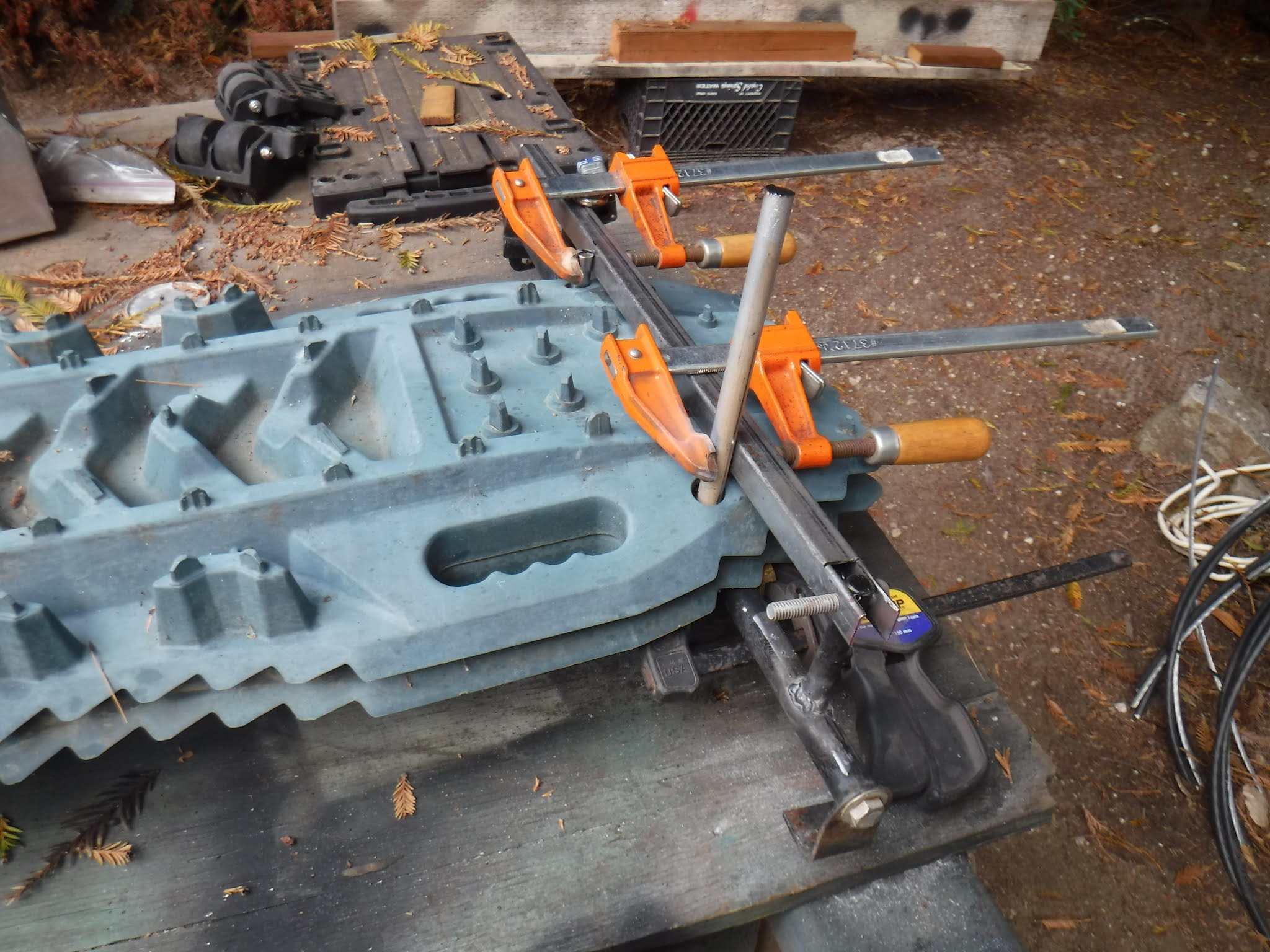
Then using a monstrosity network of clamps I welded the new pins in, one side at a time.
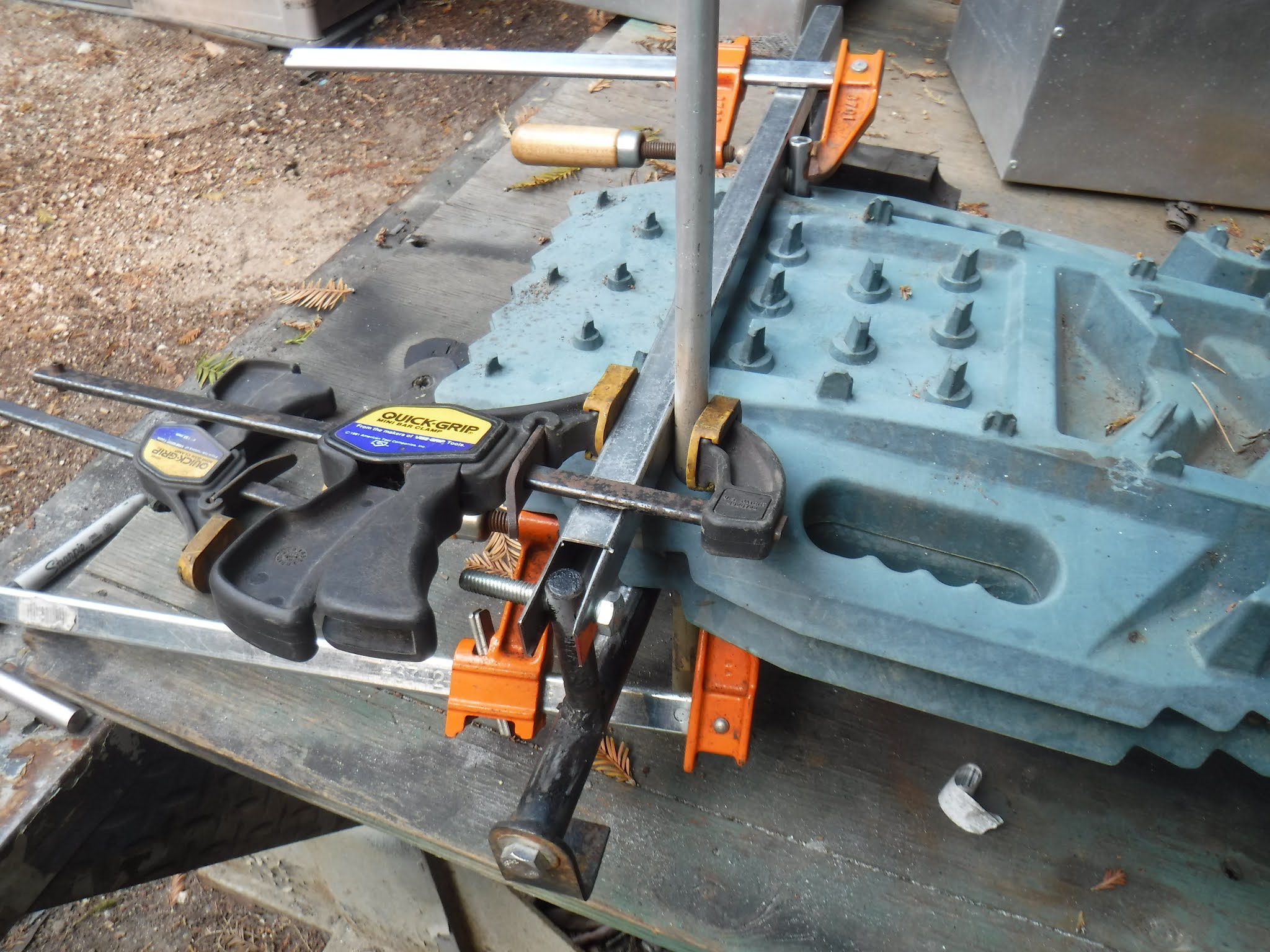


I flipped it over to see how well it fit.

WORKS FOR ME! Time for the other side.
VIOLA!

A couple looks at the job, showed some reinforcing needed to be done on the "legs".


So I cut 4 2" x 3/4 x1/8" pieces and clamped them together and finished them to size and drilled 5/16" holes thru them.


These were welded to the outside of the legs.


Once welded and reamed and finished and test fitted several times, finally both sides were done. Now it was time to fit a couple of cross braces.
20 Aug 2021
Another trip to the hardware store, I wanted some 1/2" square tubing, but they were out so I got 2 x 4' pieces as I would need around 37.75" for each cross brace.
The first one was cut and shimmed/squared into position and tack welded in place. It was a chore to get everything square.


I used some rope to pull the top square and hold it until the top brace was cut and tack welded.


After all the tacking was done, I removed the boards and did all the welding. The following pics show it open and closed.


The real test was how it was going to mount to the 109. Did all my clamping to the table keep it aligned enough?

It went on very easy AND it held the boards!


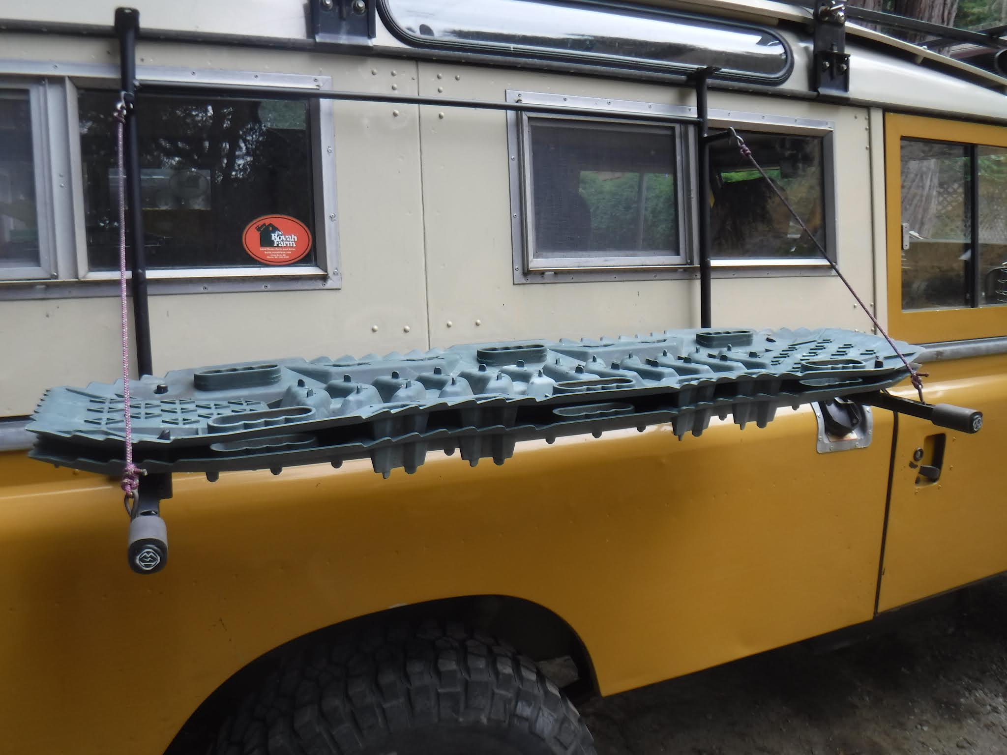
Now to figure out how to hang it in the "table" position......It needed some hooks and I had to make 4.
I scrounged around for some 3/16" rod and bent them up.


I got out some more para cord and tied the hooks on and adjusted the level. Here is a side view.

Full frontal

Some close ups of the hooks;


Then it was all dismantled and I took 1.5" off the upper ends of the clamps, they would stick out way too much when in the down position, now still will stick out but not so much. Then it was time to send it to the painter.
Oh wait! that's me too!
Flat black;

21 Aug 2021
Paint dried over night, so I mounted the back piece to the 109. Pretty straight forward at this point.

I knew that bicycle handlebars were around 3/4-7/8" in diameter and I have some rubber grip material left over so I cut some to length and slid it on. Next the grip end was fitted to the tubing. I did it I put a square peg in a round hole!


A bonus is the foam protects the 109 if the clamp bar gets dropped. Still makes a loud thump though!

Now I have a padded leverage point for closing the clamp, and it has padded ends when the "table" is open.


I went to try out the locking feature and that is where I ran into difficulties. The rear(left) side clamp would not close enough to allow the lock to close.

I did a lot of comparative measurements on the right vs the left sides. It turns out the hole for the lock is 1/8" closer to upright than the right side one. Keep in mind when I made these the hole location was not as important, it just needed to be far enough to lock above the board.
At first I thought I could remove the edge of the board that was hitting the upright. That helped a little. I finally realized with trial and error that the hole sides needed to be lower to allow the lock to turn.


I used a Dremel tool with a round grinding wheel to shape the hole, top and bottom. I went ahead and did both the left and right sides.
Then the inside hole on the clamp was wallowed out so the clamp would slide further down the pin.

Finally it would close and lock on both sides!


I am really happy with how this came out and the ease of use. I may change the hinge bolts to something like Allen or Torx head to help with anti-theft.
Love seeing your mods! brilliant work!
ReplyDeleteThank you kind stranger!
ReplyDelete