22 June 2024
Many years ago I bought an 88" Land Rover trailer. It was pretty basic, I re-enforced the tongue/frame connection and gave it a quick paint job.
Later I put on a top and painted it to match my 109, filling the holes in the bed and adding my NATO cans and keg fire pit.
This whole time I have been wishing it had brakes on it. Because my driveway is slanted I always have to block the wheel to keep it parked.
A couple of years ago I got the itch to put some sort of parking brake on. I sourced a Range Rover handbrake lever and figured I could make a cable actuated brake. How hard could it be? Lots of cars have them! I tried making a triangular wedge that would push the shoes apart and after several iterations I gave up. And it sat........
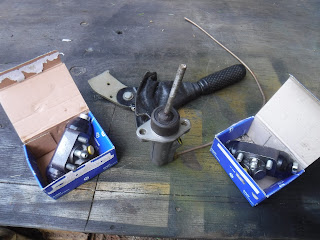
Until a couple weeks ago I decided to just replace all the missing parts for the stock brakes, wheel cylinders, shoes, pipe, master cylinder, springs. I had drums and backing plates only and 1 set of old springs. So I placed an order at Rovah Farm and parts rolled in.
I took the wheel cylinders apart and cleaned and regreased them as they will be sitting mostly.
I cleaned the backing plates and drums.
Here is when I pulled the wheel to see what exactly I still needed.
My trailer doesn't have a Rover rear axle housing(too bad would be a great place to store a spare diff), it has what I think was a trailer axle housing with fill and drain holes and flanges welded on which accept a Rover hub. I found a spare clutch m/c and figured I could make the lever push on the pushrod to work a brake.
The basics.
The m/c was taken apart and cleaned and regreased with sil-glyde and I needed to make a new pushrod. So I used my new center punch kit and drilled (somewhat off center) a threaded extension for the factory pushrod.
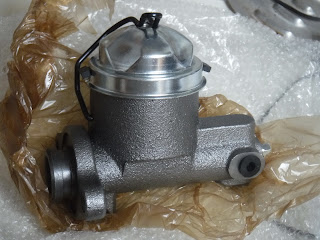
What I couldn't do with this set up was provide a fluid reservoir that was UV and rock resistant. So I went online.............I found on Amazon an all metal m/c with a 1" dia piston for an early 60's Buick brake. One of the reference # is 1372263.
In the last pic I had taken it apart and cleaned and greased it. I needed to look under the trailer and see where/how I could mount the pipes and 3-way connector, which I obtained from Rusty Goose on the Guns and Rovers Forum. Thanks Rusty!
Looking at the wheel/spring area.
Trying out a possible location for the 3-way.
The hardest bits to find were the brake line fittings, most were 3/8 -24 but the new m/c needed a 7/16 - 24 and the hardest to find was the hardline to the flex line(last pic), yet the parts were rolling in.
I obtained 2 fittings from Harvey (Bioheat on Guns and Rovers). Thanks Harvey!
Once enough stuff was impeding my workbench I went out and removed the wheels and started to piece it all together.
Jacking things up on an incline is always entertaining. In my neck of the woods one has to be careful of where you step let alone laydown or rest you head! That yellow thing is a banana slug. Trust me, you do not want to get their slime on you, it almost needs a pressure washer to remove.
It was putting on the wheel cylinder and shoes I realized I didn't have a brake shoe anchor plate. I found 1 on an old shoe so now only needed 1 more. Once again I appealed to Guns and Rovers, this time Forrester (Jim) came through. The Post office took it's own sweet time getting it from Maine to Calif, only a week and a half late.......But they got here and I cleaned and painted the 2 Jim sent and put the last piece on.
While waiting for parts, I figured out where and how to mount the master cylinder. This appeared to be the spot.
Who boy! This took a LOT of work! I had to make a cardboard template and then a thin metal plate, next a thicker metal plate, a thick rubber seal, a second thin metal plate for the outside and a thin rubber seal for the outside. With many times fitting and removing, kneeling, standing. The reason is that the front of the trailer I braced with 3/4 square tubing and covered with 1/16" sheet steel. The shape of the m/c wouldn't allow it to be flush mounted unless recessed from the front sheet.
The second recessed plate needed to have 3/4" sq tubing welded to it to space it solidly and a piece of 3/4' conveyor belt cut and shaped to fit the gap for a seal.
After the test fit the inner plate was used for the template for the outer holes and the inner seal.
I made a pushrod to,....well, push! I cut the leg off a spring U-bolt and drilled the threaded end and ground it down to fit inside the lever.
I made the hole in the outer plate too small and as the rod went thru it's arc it would hit on the top of the hole stopping movement.
So a bigger hole was needed and the whole thing had to be taken off,....again and repainted, ...again.
It was around this time I finished up the brake pipe routing, not my finest work. I wanted to bleed it and try out the system, but without that last brake anchor plate I couldn't pressurize the system.
Finally all the bits were here and installed, fluid filled and I started to figure out how to bleed it by myself. I tried a vacuum system and the threads around the bleed screw seemed to suck too much air no matter how much grease I put around them. Then I noticed the leaking fittings elsewhere, like at the 3-way and the other wheel cylinder. Pretty much all of them! One was only finger tight.......
Finally got all the leaks fixed and started to get some pressure, could only get so much though. I tried the lever, it wouldn't stay tight. The effing pawl was backwards to what I needed the fluid pressure just backed off the lever. I got my neighbor John to come up and look at things. When I applied the brake the drums would still turn and john noticed the hard line from the m/c at the flexline was dripping. When I tightened that, the threads stripped...........brand new fitting from Summit Racing. Well that ended that day.
Next day I removed the hardline and cut off the flare and removed the fitting. This time I put on an old fitting I had found. I also questioned the type of flare it needed. I had put a double flare on it and well, you know the result. This time I made a single flare on a piece of test tubing and checked the fit, seemed great, so that's what I did on the hardline. It went together fine and no leak.
I bought more brake fluid to replace that lost in leakage and rebled the system, this time I used my pressurize the m/c system. It didn't work so well as I could only get 5psi into it. But it worked!
Using the lever..............I still had hopes, I put a crapload of work into it. After farting around trying to reorient the pawls I gave up. Time to dream up something new!
I needed to push the piston in and hold it there. Lots of thoughts went through my brain. I needed simple, unbreakable, unstealable, cheap.
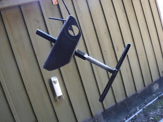
What I wound up doing was threading a 7' piece of 3/8" rod partway down, figuring out a holder for the pushrod with a threaded coupling welded to a piece of square tubing. I really, really, really wanted something quick like a lever. I settled for a "T". The way it's mounted the pushrod is in contact with the face of the piston and only needs to get screwed in about 1/2" to have the brakes fully on.
Once the shape was done I had to refine the length of the pushrod and cut about 1/2" off.
Before I finally welded it all up it was nice using my batray socket driver to put the brakes on and off and really bleed the brakes!
I had that issue with the drums turning backwards and locking up. I'll do another post on how I sorted that.
Here's some pics of the pushrod, The blue line is contact with the piston, the red line is fully engaged brakes.
And the final product;
I coated the threads with anti seize and installed it!


No comments:
Post a Comment