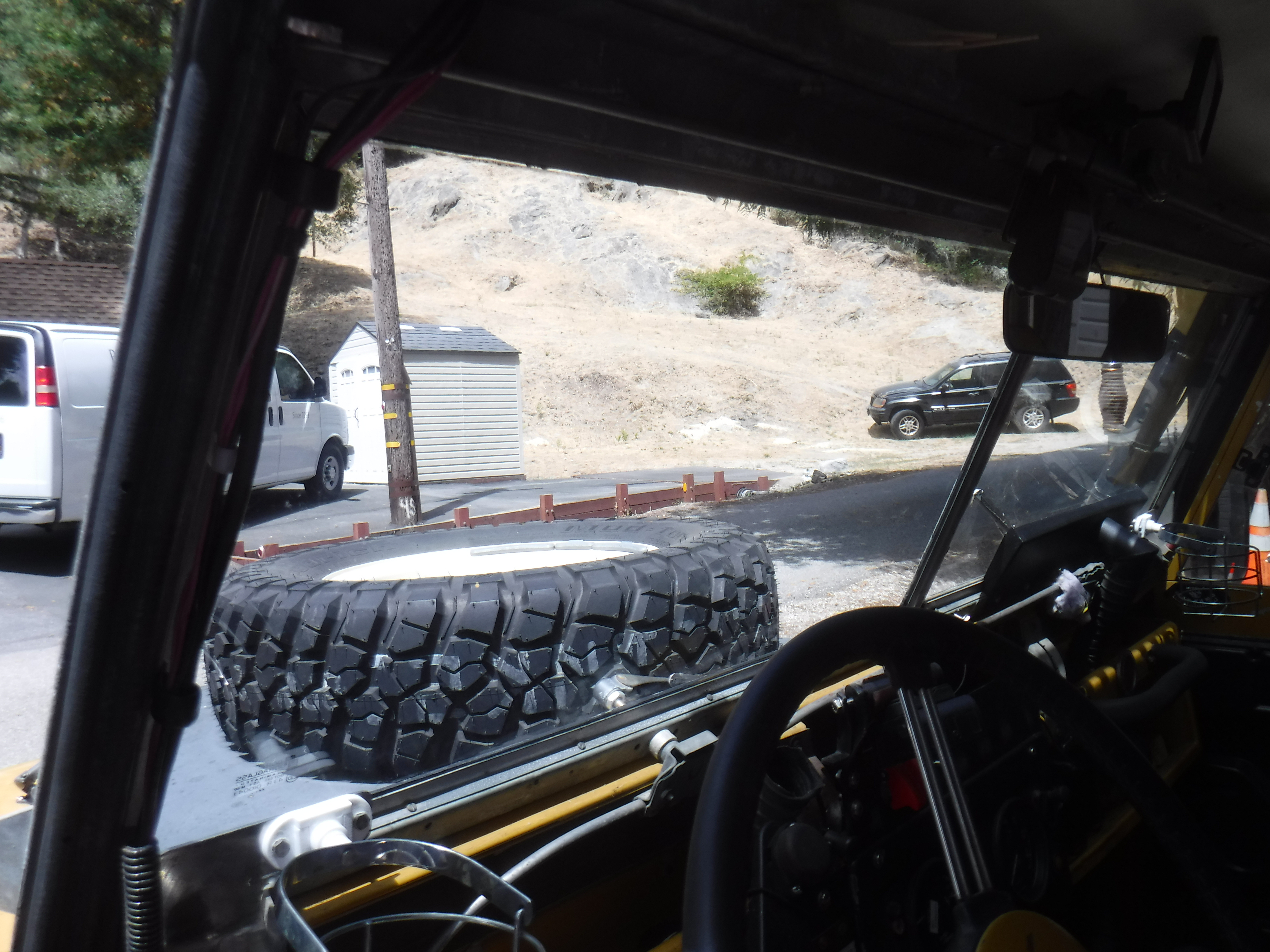
Sunday, September 1, 2024

Land Rover alternator replaced

 1 Sept 2024


     Well, this was ugly. A couple of months ago I started having starting issues. Twice in a month it failed to start. At first I thought it was because it sat too long between use. The second time was only 2 weeks after a full charge. That is when I started to really check things out. I noticed my power steering hose from the reservoir was being worn thru on the back of the alternator. I attempted to pull it away with a piece of small chain. Of course it dropped into the back of the alt and BAM I let some of the smoke out.

    I finished pulling the hose away with zip ties and figured I just fried my alternator.


Now I figured I needed to move the power steering reservoir at the same time I did the alternator. In order to make room I first needed to move the radiator overflow tank. Sheesh, Here is a before pic of where the tank was. You can see the top in the bottom of the pic.


In order to do this I needed to make a new holder and push the tank closer to the front of the grill support. It had to squeeze behind the steering box hoses.


Now I had space, making it easier to adjust fan belts too!

Dragging out the 3 spare alternators, made my  mind turn to mush or porridge if you will. Why you ask?

Because none of them were wired the same on the back and the pulley/fans on the front were all different. PLUS I didn't know if any of them were good.


 2 had keyways one didn't and all the shaft diameters were different. Mush I tell you! And I could tell that none of them were the same as the one on my engine...

Deciding the only thing to do was figure out which one I had and get another just like it. I checked my receipts and found out I bought this one Aug 2018 from Craddocks. It is an A127/65amp part number STC234. So checking around for prices I ordered one from Trevor at Rovahfarm. I also ordered 5' of 5/8"id hose for my power steering system from Grainger, along with some led's, from Superbrightleds for my instrument lights like the charge warning light when I found I had blown it out.....12v 2.2a E10 base(screw type).

Then I waited,......and thought, and waited and thought. 

My 109 would still start and run it just wasn't charging and the deep AGM marine battery would last a while because being a diesel it didn't use loads of electrics when running, only for the lights which are all LEDs.

Pondering things I decided to put in a tachometer providing my new alt was compatible. When it came in an order was put in to Speedhut for one. That meant I needed a mount. I looked around and decided right in front behind the steering wheel was the logical, read only, place to put one.

I scrounged up some alli plate I had and made some measurements, drew some lines, did some cutting and using a Smiths ammeter of the same for comparison, size cut out a hole. It mounts to the same holes I have riv-nuts in for my dash. I used some of my skills to round the top of the arch for strength and anti-vibration.


I think it will look good and I can still open the vent when it's HOT!

Laying on the ground looking up in the first pic you can see the alternator tensioning bar where it is bolted to the power steering plate. circled in blue.


In this next pic the bottom of the power steering hose I need to replace, also circled in blue.


I started this morning removing the + terminals from the battery. Then disconnecting the wires from the back of the alt. Undoing the bolt for the tensioner and taking out the pivot bolt. It was a scramble moving it around and pulling and lifting. It wouldn't get past the power steering res.

Thankfully I had moved the rad tank earlier, that gave me room. I took off the hose I needed to replace and tried wiggling again. This time I got it out!


Once out I compared the back for wiring vs the new one.


Dirty but close enough, seems they had changed the plastic. Again.

Next up was swapping the fan/pulley.

OH SHIT! It seems the shaft was around 3mm too short and I couldn't get the nut on.


Whilst messing about I discovered there are different spacers on the shafts, the old one being thinner. This spacer holds the fan away from the body.


Getting desperate and frustrated I tried the shorter one and I could bolt the pulley on! Finally!

Around a half hour later I had the alternator in.


Reran the PS hose, nowhere near the alternator.


Started it up. The charge light stayed on slightly, even with revving. I re-tensioned the belt and tried it again. It still glowed only this time brighter. I got my voltmeter out, it was only reading 12.42 across the terminals.

Something else was wrong.............

I shut it down and started cleaning up, after all lunch should have been an hour ago, all the while thinking WTF! Now I'm no electrician, I figured that some wire somewhere had melted during the chain fiasco.

Screwing my courage up and since I was already filthy I started following wires from the alt back to wherever they might go. It didn't take long. I crawled under to look at the wires to the starter and lo and behold the 2 small brown wires were just hanging there. The nut holding the battery wire that these should have been under was tight. So now it's 0435 and I am editing 'cause I remember when I had taken this wire off. A couple 3 weeks earlier I was thinking a parasitic draw might be draining the battery. I was unhooking wires and checking. This led to the chain incident and missed hooking them back on.........

I grabbed a 1/2" wrench and put it back on feeling much chagrined, for my ineptitude and time and $ spent.

Once it was affixed properly I restarted the engine and the charge light went out! I stopped it and put in one of the leds and restarted, the light stayed on and my ammeter showed 12.4v. So I stopped the engine again and put in the incandescent bulb, restarted and 14v+ on the gauge.


Now I have to wait on the tach.

So I learned the LEDs won't work on the charge lamp socket, they do on the oil press lamp. That I'm an untrustworthy mechanic and need to check my work. That hot showers still feel good! That my original alternator is probably still good.

Tuesday, August 13, 2024

Series 2 Land Rover windscreen glass replacement

 11 Aug 2024

   Over the last year or so I noticed that my windscreen was almost impossible to see through when heading into the sun. So I reached out to Trevor at Rovahfarm and ordered 2 pieces of glass for the windscreen. I bought the laminated #MTC5318.

   It arrived unscathed and sat until the weather cooled off. I wasn't going to do this in 104F+! And Today it was cooler, only got up to 90F......

Here is the start out pic, lots to remove!


It took a few trips to the garage to get the correct tools to remove bits in the way. Eventually I got the drivers side out;


The old glass on the work table


The chaos of tools and bits.........


I unwrapped the new glass, boy is it clear!


Then installed it. It was slightly larger than the old glass and fit very good. Surprisingly for Britpart.


At times it was a bit awkward doing it by myself and trying to put in those tiny screws and hold the glass in place at the same time, it is doable. I found some corrosion in the tubes for my defroster vent and it took some time to clean and paint the inside. 

13 Aug 2024

   On this cool morning I tackled the passenger side glass. Now I had a sequence to follow, starting with loosening the wiper arm followed by removing the rearview mirror, defroster vent and cup holder. I took care of the defroster tube corrosion first so the paint could dry while I swapped the glass. Next was a matter of removing all the side strips and the putty around the glass and pressing a corner of the glass until it started to move.

    Once the glass was out I used a putty knife to clean out the windscreen frame and ran a wire wheel on a drill around it to clean it up. Over at the workbench I cleaned the putty off the strips and wire wheeled them clean and tapped the screw holes flat with a hammer. I also marked each strip as to where it went and it's relation to the door with marking pen on the underside.

    There was a lot less stuff in the way of the passenger side so it went quickly. I used 3M strip caulk to reseal the opening by laying a strip along the inside of it all the way around and then fitting the glass. I found that when it was too hot the strip caulk was too hard to get off the paper it coms on and sticks EVERYWHERE! If I wetted my fingers, I licked mine, the caulk would not stick to them. I also froze them overnight so I could separate the paper layers in the box.

At the start today;


Now both sides are done!


It did look like the drivers side had been replaced at some time as the caulk in both sides was different, the passenger side being more dry and brittle.

Sunday, June 23, 2024

Land Rover sticky brake shoes

 23 June 2024

      For a while now folks have been dealing with sticking brake shoes after replacing the shoes and sometimes the shoes and drums. The drums rotate fine when going forward and lock on when in reverse. I put the fault at substandard parts.

     Now with my trailer brakes I get to experience it first hand. And here is what I found out and how I fixed the issue.

   For a while now the advice was to just chamfer the leading edge of the trailing shoe. With that in mind when I put on my new shoes I chamfered the leading edge on both shoes. paying more attention to the trailing shoe. Oddly I only had the issue on one brake.

Here is the initial setup before I did anything.


The first thing I found was it didn't stick until I tightened the screws in the drum and mine was sticking when rotating forward. Then I used my angle grinder to remove some of the material off the shoes.


Back on it went;


Still it stuck. I removed the drum and really began to check things out. I noticed that even with no fluid pressure the front piston was coming out further. I pushed and pulled to make them equal and the rear went in and the front out, every time. Something in the cylinder? I even opened the bleed screw to let any pressure out.


Next suspecting the pad to be part of the issue with an improper curve or thickness I began a series of rotating the drum, causing a scuff on the pad and then grinding or filing the pad down at the scuff mark. In the pics the scuff mark is darker and the filing is lighter. Each time the screws had to be tightened and removed, by the time this day was done my right thumb needed icing!


The last scuff was this one and after the subsequent material removal it freely turned in both directions.


So for me in this 1 instance I put it to being what ever is causing the piston to push out and not stay retracted and the shape of the pad against the drum. Since the drums are old I don't know how true they are either.

On another front I took a couple of old aluminum wheel cylinders apart to recycle them. Here's the pics.


Saturday, June 22, 2024

Land Rover trailer, parking brake?

 22 June 2024

    Many years ago I bought an 88" Land Rover trailer. It was pretty basic, I re-enforced the tongue/frame connection and gave it a quick paint job.


Later I put on a top and painted it to match my 109, filling the holes in the bed and adding my NATO cans and keg fire pit.


This whole time I have been wishing it had brakes on it. Because my driveway is slanted I always have to block the wheel to keep it parked.

A couple of years ago I got the itch to put some sort of parking brake on. I sourced a Range Rover handbrake lever and figured I could make a cable actuated brake. How hard could it be? Lots of cars have them! I tried making a triangular wedge that would push the shoes apart and after several iterations I gave up. And it sat........

Until a couple weeks ago I decided to just replace all the missing parts for the stock brakes, wheel cylinders, shoes, pipe, master cylinder, springs. I had drums and backing plates only and 1 set of old springs. So I placed an order at Rovah Farm and parts rolled in.

 I took the wheel cylinders apart and cleaned and regreased them as they will be sitting mostly.


   I cleaned the backing plates and drums.

Here is when I pulled the wheel to see what exactly I still needed.


    My trailer doesn't have a Rover rear axle housing(too bad would be a great place to store a spare diff), it has what I think was a trailer axle housing with fill and drain holes and flanges welded on which accept a Rover hub. I found a spare clutch m/c and figured I could make the lever push on the pushrod to work a brake.

The basics.


   The m/c was taken apart and cleaned and regreased with sil-glyde and I needed to make a new pushrod. So I used my new center punch kit and drilled (somewhat off center) a threaded extension for the factory pushrod.


    What I couldn't do with this set up was provide a fluid reservoir that was UV and rock resistant. So I went online.............I found on Amazon an all metal m/c with a 1" dia piston for an early 60's Buick brake. One of the reference # is 1372263.


In the last pic I had taken it apart and cleaned and greased it. I needed to look under the trailer and see where/how I could mount the pipes and 3-way connector, which I obtained from Rusty Goose on the Guns and Rovers Forum. Thanks Rusty!

Looking at the wheel/spring area.


Trying out a possible location for the 3-way.


The hardest bits to find were the brake line fittings, most were 3/8 -24 but the new m/c needed a 7/16 - 24 and the hardest to find was the hardline to the flex line(last pic), yet the parts were rolling in.


I obtained 2 fittings from Harvey (Bioheat on Guns and Rovers). Thanks Harvey!


Once enough stuff was impeding my workbench I went out and removed the wheels and started to piece it all together.


Jacking things up on an incline is always entertaining. In my neck of the woods one has to be careful of where you step let alone laydown or rest you head! That yellow thing is a banana slug. Trust me, you do not want to get their slime on you, it almost needs a pressure washer to remove.


It was putting on the wheel cylinder and shoes I realized I didn't have a brake shoe anchor plate. I found 1 on an old shoe so now only needed 1 more. Once again I appealed to Guns and Rovers, this time Forrester (Jim) came through. The Post office took it's own sweet time getting it from Maine to Calif, only a week and a half late.......But they got here and I cleaned and painted the 2 Jim sent and put the last piece on.


   While waiting for parts, I figured out where and how to mount the master cylinder. This appeared to be the spot.


Who boy! This took a LOT of work! I had to make a cardboard template and then a thin metal plate, next a thicker metal plate, a thick rubber seal, a second thin metal plate for the outside and a thin rubber seal for the outside. With many times fitting and removing, kneeling, standing. The reason is that the front of the trailer I braced with 3/4 square tubing and covered with 1/16" sheet steel. The shape of the m/c wouldn't allow it to be flush mounted unless recessed from the front sheet.

The second recessed plate needed to have 3/4" sq tubing welded to it to space it solidly and a  piece of 3/4' conveyor belt cut and shaped to fit the gap for a seal.


 After the test fit the inner plate was used for the template for the outer holes and the inner seal.


I made a pushrod to,....well, push! I cut the leg off a spring U-bolt and drilled the threaded end and ground it down to fit inside the lever.


I made the hole in the outer plate too small and as the rod went thru it's arc it would hit on the top of the hole stopping movement.


So a bigger hole was needed and the whole thing had to be taken off,....again and repainted, ...again.


It was around this time I finished up the brake pipe routing, not my finest work. I wanted to bleed it and try out the system, but without that last brake anchor plate I couldn't pressurize the system.


Finally all the bits were here and installed, fluid filled and I started to figure out how to bleed it by myself. I tried a vacuum system and the threads around the bleed screw seemed to suck too much air no matter how much grease I put around them. Then I noticed the leaking fittings elsewhere, like at the 3-way and the other wheel cylinder. Pretty much all of them! One was only finger tight.......

    Finally got all the leaks fixed and started to get some pressure, could only get so much though. I tried the lever, it wouldn't stay tight. The effing pawl was backwards to what I needed the fluid pressure just backed off the lever. I got my neighbor John to come up and look at things. When I applied the brake the drums would still turn and john noticed the hard line from the m/c at the flexline was dripping. When I tightened that, the threads stripped...........brand new fitting from Summit Racing. Well that ended that day.

    Next day I removed the hardline and cut off the flare and removed the fitting. This time I put on an old fitting I had found. I also questioned the type of flare it needed. I had put a double flare on it and well, you know the result. This time I made a single flare on a piece of test tubing and checked the fit, seemed great, so that's what I did on the hardline. It went together fine and no leak.


    I bought more brake fluid to replace that lost in leakage and rebled the system, this time I used my pressurize the m/c system. It didn't work so well as I could only get 5psi into it. But it worked!

    Using the lever..............I still had hopes, I put a crapload of work into it. After farting around trying to reorient the pawls I gave up. Time to dream up something new!

    I needed to push the piston in and hold it there. Lots of thoughts went through my brain. I needed simple, unbreakable, unstealable, cheap.

    What I wound up doing was threading a 7' piece of 3/8" rod partway down, figuring out a holder for the pushrod with a threaded coupling welded to a piece of square tubing. I really, really, really wanted something quick like a lever. I settled for a "T". The way it's mounted the pushrod is in contact with the face of the piston and only needs to get screwed in about 1/2" to have the brakes fully on.


Once the shape was done I had to refine the length of the pushrod and cut about 1/2" off.


Before I finally welded it all up it was nice using my batray socket driver to put the brakes on and off and really bleed the brakes!


I had that issue with the drums turning backwards and locking up. I'll do another post on how I sorted that.

Here's some pics of the pushrod, The blue line is contact with the piston, the red line is fully engaged brakes.


And the final product;


I coated the threads with anti seize and installed it!