Friday, May 3, 2019

10L NATO can carrier

I bought a couple of 10L NATO cans to carry engine oil and 90w gear oil on my trips. My thinking is that they will be less likely to spring a leak as the plastic gallon containers.
  I have been using a gallon container for decades with the pump that goes in the opening. Very messy! To contain the mess I have kept mine when not in use in an old ammo can that I did not have a lid for. So my first thought was that I could just use the ammo can to hold the NATO can. After all it fit snugly fore and aft but there was a side gap.


So I spent some time making the ammo can mo betta' by removing the hinges and locking bits for my non-existent lid.


Then I fitted it with some angle iron I welded to the bottom and drilled and tapped mounting holes in my trailers frame.


During all that I realized I only had the 1 ammo can and 2 of the 10L cans and I didn't like the way the mount was going to be on the trailer. So I thought of something else.

I decided to make something that would hold 2 NATO cans across the front of my trailer. I would design it similar to the old NATO can holders, the black one seen on the left.


I started by demo-ing a jig I had made of angle iron and making a base for the cans. I used angle for the corner uprights;


Around the top I put some 1/8" x 1" flat. This I formed around the base to keep the dimensions and shape the same. That ended day 2.


As usual all along I test fitted both the can and the frame to trailer.


I put in some cross strips to stiffen and help with anti-theft. and vertical strips for the same reasons.The frame was tested and spots marked for mounting braces to lift the front of the frame and bolt it to the trailer.


Once these were on I clamped it all together and drilled holes for thru bolts in the frame and chassis. For bolts I used some 8mm x 1.25 x 100mm that I had mis-purchased during my 109 build.


With mounting holes done I welded a hasp on one end for the locking part over the spout end of the can.
Painted it up to prevent overnight rust.

  And that was day 2.

Day 3 saw me again mount up the carrier and make some mounting brackets for the back of the carrier. Once made and measurements taken it was dis-assembled (again) and the brackets welded on.


Then it was remounted and holes drilled for the new brackets. The cross member is 5" thick and I didn't have any bolts long enough to thru bolt.


So I tapped the chassis for 1/4-28 bolts.


The brackets were welded on;


Then came the hard part; I need to make a strip to go across the top of the can and cover the spout. I welded the end of the locking hasp to the end of the 1" flat stock.


Then with the can in place I proceeded to bend up the right shape by some majickery I don't understand and amazingly the first one came out perfect.....


I dunno......so I welded a hinge to the inside frame and the locking strip.
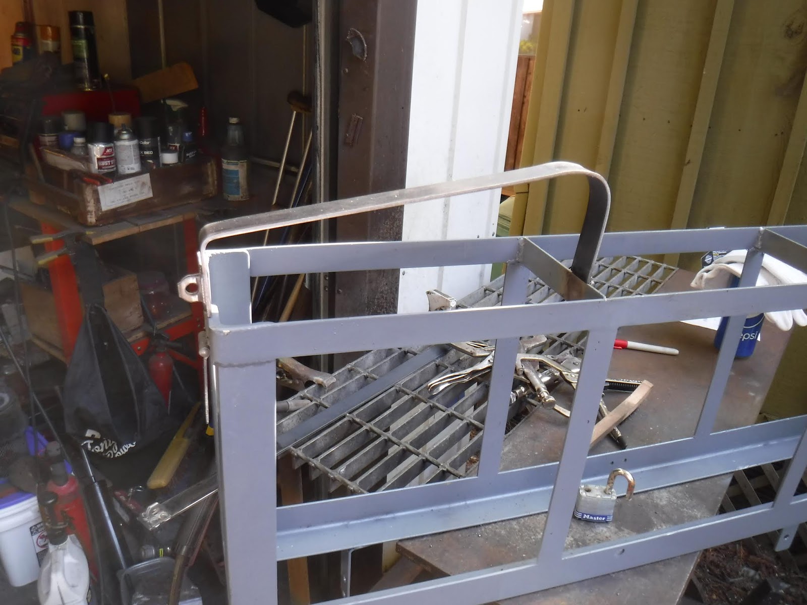


The second one took more sweat equity and doesn't fit as nice as #1, but it will take a keen eye to see it. Once all the welding was done painting ensued.


I used Machinery gray, primer and paint all in one.  Once dry.............drum roll................


I think that I will have to remove the front center section to refit my kegger bbq. It is at the welders getting some appendages put on it. It had been my hope that I could either fit a third can(too fat) or a theft proof box there for spouts and funnels etc...

Sunday, April 21, 2019

Land Rover spare tire cover

Well, not quite what you think. I got tired of all the duff falling from the trees and sitting in my wheel getting wet and staining the paint. I've seen where other peoples had made wooden covers for their wheels so I figured I could too.

   First I measured the rim, I have 16" rims and they need 18" to cover the OD. I then searched for some wood scrap and found some plywood that was over 18". Then I needed to make a  18" circle. Probably could have done it with a pencil and string but I looked around for something I might have that was the right size. Looked at bucket lids and garbage can lids and finally found a supersized flying disc from the 80's.

   I used this to draw the circle around;


Then I cut it out with my jigsaw;


And used the router to make the top edge rounded;


I spent a little time sanding it all down to make nice...:


It didn't get rid of all the oil but it made it smoother;


Then a test fit on the spare;


The test fit included measurements for where to drill holes for my "J" hooks, these were intended to be my hold downs, since they work for batteries they should work for this. I found that I needed to drill my hole 7" from the edge. Once drilled the j hook needed 2 nuts and washers to work as I needed.


Test fitting with the 1 j hook;


The j hook was too long but it was holding well and lined up good so I cut it down and added the second j hook. A quick test showed the 7" location worked well. with the J hook I welded the bottom nut to the bottom of the threads so the hook would not pull thru. I left about 2" above the top wingnut so I could manipulate the hook when installing and removing the cover.


Then I painted it.


And painted;


Lots of coats, and once dry installed it.


Now I have a compartment under the cover for something like rope. I'll see in the long run if it works out. Who knows if it will hold up under the weather.

Thursday, April 18, 2019

Series 3 Brake light switch

   Since I went with the disc brake conversion I use a Series 3 dual brake system and that includes a servo. With this set up the brake light switch is mounted on the pedal tower.

Mine went out, I know not when, I found out just doing a check.

I pulled the old one apart to see what went wrong and if it was repairable. AFTER I ordered 2 new ones from Rovahfarm. Part # 575166.

It appears that the switch has plenty of heat and the plastic melted and covered the contact. I don't know if this is the side with constant 12v. In the process I destroyed the switch as the brass is crimped over the plastic and I cut it off with a dremel tool.

Where the switch mounts;


What it looks like;


inside the brass looking at the contact ring;


Inside the plastic looking at the contacts;


The contact ring out of the body;


An exploded view;


A few days later;

Based on online advice I put a relay in the circuit. Now I just have to wait for the switch to show up.


I took power off the switch power wire and jumped it over to Terminal 30. I hooked the switch outlet(the control power) to the 86 terminal. the 85 terminal goes to ground with a black wire. The old switch outlet wire now comes off the 87 terminal.

To do all this I looked at my S3 workshop manual and can't find how to adjust the depth of the switch. This led me to pulling off my switch plate to try to figure out how it all works. I still don't know......

My manual just shows a flat plate, I have this;


Defender?  I used my dial calipers to check for movement of the switch lever and it is really small, .025. But then the switch doesn't move all that much either. I'll figure it out.

Welp, I got 2 switches and I figured I would have a spare. I didn't think I would need it so soon. The first one I tried would make the brake lights come on but they would not go off....

Here is one of the new switches;


Here I am showing the plunger open and depressed;


I used my test light to check the switch coming on as the brake pedal was depressed.


I was going to wire in a relay that you can see I mounted on the back wall, but it too would not turn the lights off when the pedal was released, so I went with the original wiring.

Now this story is not over, I have decided that the LR switch is too iffy and have decided to change my set up. I have ordered a pull-to-on switch that goes to a motorcycle rear brake. This will hook via a spring to the brake pedal in the footwell and replace the push-to-on switch at the top of the pedal. Motorcycle rear brake switches are durable as they are made to be in all kinds of weather and cycle for thousands of  brake applications.

Update May 2019;

    I did not waste any time I didn't want this switch to fail without me knowing. So I ordered the same rear brake switch as on my 2008 Suzuki DL650 Vstrom.  I found good pricing online at Babbitt's Online. I purchased a switch # 37740-31D00 and pull spring #09443-06012. with shipping @$36.
   They came yesterday and as I was busy with the NATO can carrier it put it on today.

Here is how;

    starting with seeing how it fit in the area and what type of bracket I would need and where it would attach;


    I figured I could go off the single bolt for the pedal box with a 90° angle of some 1/8" x 1" flat stock. The switch has an adjuster nut that presses into a hole in the brake pedal bracket on the bike. So I drilled a 5/8" hole in the end of some flat.


Next I figured out about how far away I need to bend the 90 and then drilled a 5/16" hole further than that for the bolt. Put it in my vise and hammered it over to a 90. Then cut off the excess which I left a little long in case I needed to move the switch farther away with more holes. Then test fit and see where to run the wires, the switch wires were easy in the next pic you can see an oblong hole in the parcel tray lower, I planned to use that.


I needed to get the 2 green wires in the next pic thru the bulkhead where the 2 red wires passed thru.


I took the dash off and ran the switch wires under the steering column mount.


Then came the hard part, getting the wires thru 2 sections of the bulkhead. I tried pushing one thru but it was too tight. So I figured I would push an ice pick thru and tape the wires to it and pull them thru. Well think again genocache, as the ice pick just pulled out of the tape. So I tried 1 wire at a time. NOT! Tape still pulled off.


Evidently all my ice picking widened the gap a little and I was finally able to just shove the wires thru 1 at a time.  :^)  Now the players were all on the same field!


New connectors were used, I used the Posi-tap connectors(blue).


I adjusted the switch so there is no pull when the pedal is up and it pulls out when the pedal moves.


Let there be light!


The engine bay wiring looks like;


After the bracket was cleaned up and painted the footwell looks like;


The spring is connected to the bottom of the pedal return spring. Here is the new switch in the closed position;


And open position;


Hoping this won't ever need to be redone in my lifetime.