Wednesday, March 20, 2013

misc Land Rover 109 stuff

Ok yesterday I got my lengthened steering link back from the welder. We added 9in to the center with some cold rolled mild steel rod. The welder, Daren of ArcTec in Santa Cruz, took a 16" bar rod and turned 4" down on each end to fit inside the split stock steering link. Then he welded the seam and drilled and put in welds into the inner shafts to make it stronger.

I brought it home and cleaned it up and sprayed it with black bed liner from Duplicolor. The same stuff I've used elsewhere. It was not dry enough to install today.

So instead I worked on making a large guage/switch panel to fit the right side of the steering column. I used an old small panel as a template and using some measurements made a new panel out of a piece of aluminum I had laying around. Once it was shaped and bent I marked the holes and drilled everything out. Then with my rivenut tool I put in 3 of them to hold the panel in place. Now I just have to figure out what to put in it!

So before drilling any holes I've covered it with the truck bed liner ;^) Just hoping to keep it from getting scratched.

After that was made I went to task on my demisters. Last week I discovered that I couldn't use any of the one's I have because of the interference of the single motor wiper system that's been installed. To make it work I hade to make the RH one 5/8" taller from between the screw holes to the hose opening. Not done yet so there are no pics. I am not sure if I will make the LH side larger or not to match. Still have to put in the hose hole and figure out the connection for it. Plus strip and repaint the old seatbase lid I made it out of.

Friday, March 15, 2013

Horn for the 109

Well, I was ill for a week with a cold so that took me out of my stride. Was actually about 9 days to feel 100% again.
I put an airhorn on my Land Rover. No not one of the great huge things. A small one that's loud and distinctive. I had put one(Stiebel) previously on my Suzuki DL650 V-Strom and it works a peach!
I bought one at my FLAPS(Friendly local auto parts store) O'Reilly's. This one was a "Bad boy" brand.

In order to mount it I had to find the horn wiring in the loom and figure the mounting from there. I was able to put it in front of the battery, bolted to the battery tray. The horn system is a one wire circuit from the horn button with the ground going thru the horn motor/housing. Easy peasy.


I bought an aluminum hawse for my winch and put it on. I then stamped my winch, bumper and hawse with my last name incase of theft.


I ordered a valve for my brake servo so the vacuum pump could be hooked up. Well it came in this week and turns out it don't fit! WTF? The new valve is too large to even go into the bare hole let alone with a seal. I'm currently checking with the supplier about different sizes. The supplier of my servo listed it as coming off a 1983 Land Rover Series 3. The pics show the old and new seals, old one has the smaller end hole, and the valve fitment to the servo. I don't find anything online about 2 sizes............when will it end?

Been having issues with the wiring loom too...............the brake wiring was set up for RHD not LHD. The wiring in the dash ends with mostly ring terminals----all the switches are spade connectors....To do it all over again I'd build my own loom and forget Autosparks and thier US pawn British Wiring. On the good side Autosparks has been answering some of my email questions.
I feel over my head with the wiring. There are some wires not listed in the diagrams in the loom and some in the diagrams not in the loom. Total SNAFU in my book. But between the Series 2-2a-3-110(19j motor) wiring diagrams I am getting some of it worked out. I now have brake lights that function off the pedal, headlights(not sure the dip switch works right) and running lights front and rear. I may need to pay for help.

Sunday, March 3, 2013

front 109 wing fittment

Ok so the fittment of the LH front wing was undertaken.  The first thing I did was the wingtop modification of cutting an access panel at the rear of the wingtop. This is above the clutch and brake master cylinders on LHD models. It affords easier access to the master cylinders and pedal towers without having to remove the entire wing. There is also improved access to the bolts holding the wing to the bulkhead and the mudshield.

     To do this I looked at the underside and measured out how far I could go with a panel. Over the years of Land Rover ownership I have discovered that the bigger the access the easier it is to do the work. You have to watch out for the mudshield bracket on the underside of the wingtop. I settled for 1 foot(12inches) on this job.

     The foot mark was transferred to the top surface and tape layed out on the line and next to it to keep the paint from getting marked up. Then a jigsaw was used to cut the wingtop.


     I had previously secured some flat aluminium stock for my connecting bracket. I predrilled it for 1/4" holes for the bolts and 1/8" holes to locate the 3/16" pop rivets I was going to use. The 1/4" holes were tapped with 1/4-28 thread. With these in hand I marked the 1/4 hole locations on the top and drilled out the holes. Removed the side bolts from the access panel and then bolted the bracket in place. At this time I have to tell you that the bolts need to go in the front part of the wingtop and the pop rivets in the access panel. This prevents the new bracket from protruding into the access space( Don't ask me how I know).

    So with the panel clamped and bolted in place the pop rivet holes were enlarged to 3/16 and the rivets put in.

    The wing to bulkhead bolts were installed so the wing could be fitted. Then I removed the top and bottom ones as they are not a slide fit into the wing. The new access panel was left on and a bolt put in upside down in the top mounting bracket to locate the wingtop, allowing the wing to hang in position.

     So the next process was hang the wing, mark the area needing to be cut around the steering box, remove the wing, cut the wing, refit the wing, see where there was interference and mark the wing, remove the wing, cut the wing, refit the wing, see if there was any interference and mark the wing, remove the wing, cut the wing, refit the wing, see if there was any interference, mark the wing........well you get the idea. Lots of fettling around the steering box and the lower steering column.

    Even with all the fettling I screwed up and made one section too large an opening. Solving this was as simple as pop riveting the cut off section to fit the needed opening.

 It is not permantly mounted because I still need access to the electrics on that side but it does fit.

Monday, February 25, 2013

Land Rover inspection sockets


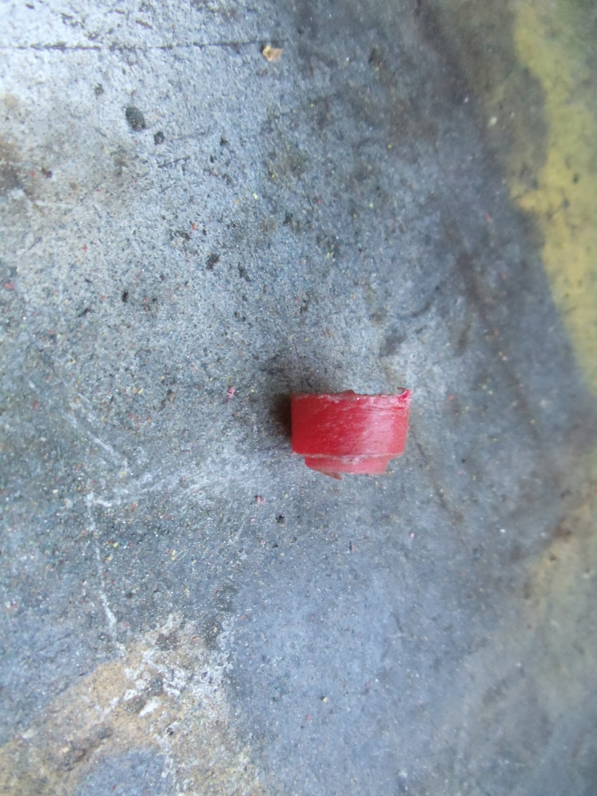
Hey, I spent part of the day refurbishing my old broken inspection sockets. What I did was take the old ones apart and figure what I had lying around to make new ones with. Deciding on some 1/4"ID rubber hose for the black(ground) side witha a 1/2" OD. The holes in the dash were .44 so I used my Dremel tool to grind off some of the OD on the tubing and again on the ID to make the recess for the  socket to sit slightly below the level of the front. The hard bit was finding something red and insulating for the power(positive) side. Looking around I found and old bent screwdriver with a red plastic handle. Putting the shaft in my cordless Bosch drill I ground the handle round down to the half inch diameter needed. Then with a hacksaw I cut off the required cross section and put it in my vise for my Craftsman bench drill press. I used a 1/4" drill to put a thru hole and a 21/64 for the countersink. again the Dremel was used to cut the lip for the inset of the hole. The liberal use of a fine file made the base low enough to fit the thickness of the dash. Too thick and it won't tighten up.

Friday, February 22, 2013

Blog changes

Google has made some changes to how Blogger works. It is more difficult for me to post up pics, I can no longer put them left, right, center. When they do upload they go to some random place in the text and I have to cut and paste them to the correct location. Some times it takes repeated attempts to upload for success. I can no longer indent paragraphs or space them apart. Just frustrating.

109 wiper moter cover


Well, I put in some Rivnuts to hold the wiper motor cover plate. I used 10-32 Rivenuts, they are the same size as the screws which hold the top of the dash in position.(IIRC) I used a Rivet Nut Tool from www.rivetnuttool.com. I like the ease of use and the cost for this occasionally used tool for the handyman. So once I decided on the size to use I drilled out the hole and filed a small notch in the hole to keep the rivenut from turning. Then I put the rivenut on the tool and inserted it in the hole and pulled the slide up tight! Presto the rivnut was installed! I also put the drivers seat in. Again I used 2 thick stainless washers in the front and 1 in the rear. Next was to put in the lid for the underseat box. That was when I found out I had used the wrong lid. I restored a used lid I had instead of the orginal lid thinking they were all the same size. The orginal lid had the hinges at the rear and with the Defender seats I would not be able to lift the lid for access. Well the "new" lid braces on the inside are 1" wider than the opening to the box. So the old lid was dug out, the hinges removed and paint removed. Primered with self etching primer from Duplicolor dried overnight and sprayed with Duplicolor Caterpillar yellow paint. Now this is the NEW Cat yellow and not a match for the OLD Cat I used on the 109. But it was easier and mostly hidden under the seat. Once the lid was in I discovered I would need an additional thick washer in the front on the left side for the slide arm to clear the lid when lifted in the sliding position. Then the seat cushion was installed and I climbed aboard. I find the command position higher in the drivers side than my 88 with stock seats. Not a big deal unless at a stop light. Maybe I can figure a mirror system to see the lights. Here's a pic with both the seats installed.

Thursday, February 14, 2013

109 battery

I finally got the battery in. It took 4 days to do it what with fab work and painting. I had cut the old battery tray off prior to galvanizing with the intention of hopefully being able to put it back on in the same place. In thinking of this I left some stubs of the old battery supports and predrilled holes. At the same time I predrilled holes in the leg portion still connected to the tray. Then every thing went to the galvanizers last year and the holes would be more protected from rusting out.
So now I just found some 1/8x1" angle iron and cut out some sections and lined them up on the bottom stubs and marked the hole position. Then the centerpunch and drills put the holes in the right places.
Once these were bolted in I put the upper tray in place and marked the holes for the angle iron. Removed them from the stubs and again centerpunched and drilled them. Then mounted the upper to the lower to make sure it fit. Then took everything apart. The angle braces were cleaned, treated with rust converter and painted with cold galvanizing. I then had to devise a side support for the battery that would also hold the J hooks to keep the battery from moving. After looking at my 88 I got a piece of 1/8x2" 4 feet long. With this I could bolt onto the upper tray portion and have sides for the battery to not slide off and put in holes for the J hooks. A centerline was put on the strip of steel and I decided to put my weld at one of the narrow ends. So starting back from one end of the steel, the upper section was placed and marked for holes.
These were centerpunched and drilled and the tray bolted in. Then a pencil mark was made for the next bend and the upper part unbolted. I used a carpenters square and made a 90deg marks across the steel. This would be a reference for the bend. Next the steel was slide in the jaws of my vise with the pencil line just above the jaws. I used my propane torch to heat the metal right at the jawline and using my hand and a hammer I bent the steel into a right angle. Back over to the table and rebolt the upper section and mark where the next bend would be for the long side bit. Unbolt. Back over to the vise and heat and bend.
Back over to the table and bolt the 2 sections together again. Mark the holes and the next bend, unbolt. Centerpunch and drill holes. Put in vise and heat and bend the last corner. At this point the ends overlap but first I needed to bolt the 2 sections together again. Then the mark was made for the place to cut off the overlap, which was done by a jigsaw after unbolting the 2 pieces. I clamped the ends together and welded up the seam. Then bolted the 2 back together and took then to try out on the 109. Everything worked out great!
So it was all unbolted. The side support was wire brushed, sprayed with rust converter then sprayed with bed liner, 2 coats. A measurment was taken at some point for the length of J hook and a trip made to the FLAPS(friendly local auto parts store) Boulder Creek Auto Parts a NAPA dealer. Here J hooks and a top support were purchased. It turned out the top support wasn't a good fit, it would be too weak for holding a battery down off road. I imagine it was fine for a road car but not for washboard roads. That meant one had to be made. For this I used some 1/8x3/4" angle iron connected across the battery by a piece of 1/8x1" flat stock. I mocked them up, marked and measured, cut and centerpunched and drilled, welded and finally test fit and wire brushed. Then sprayed with rust converter and 2 coats of bed liner. Once everything was dry I bolted it on to the chassis stubs and put the battery on.
Then attached the ground from the negative side to the engine.